Method of measuring axial force of bolt and instrument for measuring axial force of bolt

a technology of axial force and measurement method, which is applied in the direction of force measurement, force measurement, instruments, etc., can solve the problems of certain degree of skill, difficult to obtain stably measured results with high accuracy, and adopt these methods, etc., to achieve the effect of reducing the pressure chamber pressure time, easy measurement, and good accuracy

Inactive Publication Date: 2011-07-28
IMAI ATSUSHI +4
View PDF2 Cites 28 Cited by
  • Summary
  • Abstract
  • Description
  • Claims
  • Application Information

AI Technical Summary

Benefits of technology

[0011]An object of the present invention is to provide a bolt-axial-force measuring method, and a bolt-axial-force measuring instrument, which are capable of easily and precisely measuring the axial forces of the bolts.
[0023]According to the present invention, when the axial force is generated by using the tension means actuated by the hydraulic pressure to add the tensile force to the bolt, a value of the hydraulic pressure plus the pressure receiving area of the pressure chamber in the tension means is equivalent to the bolt axial force. Such equivalence is used to add the tensile force to the bolt by the above tension means and to transfer, to the nut etc., the axial force applied by the tension means to put the bolt into a fastened state. In this process, the inflection point where the change rate of the pressure change inside the pressure chamber of the tension means is suddenly reduced is detected, and a value obtained by multiplying the pressure value of the pressure chamber at this inflection point by the pressure receiving area of the tension means is calculated as the axial force of the bolt fastened. Therefore, a difference between the lengths of the before-fastened bolt and the after-fastened bolt is not measured unlike the ultrasonic method and the measuring stick method, and the bolt axial force can be directly measured, so that variation factors which may influence the measurement accuracy of the blot axial force are reduced to the utmost, whereby the bolt axial force can be easily measured with good accuracy. As the tension means, the bolt tensioner and the fluid pressure nut that are activated with a fluid pressure (hydraulic pressure) can be used.
[0024]According to the present invention, the fluid pressure in the pressure chamber is discharged while being reduced by using the pressure reducing means, whereby the pressure reducing time of the pressure chamber is prolonged. For this reason, the detection of the inflection point is made easy, and the detection accuracy thereof can be enhanced. Further, since a low-cost apparatus constituted from a simple circuit(s) can be used as an apparatus for detecting the inflection point, a cost of the apparatus can be reduced.
[0025]According to the present invention, the plurality of tension means corresponding to the plurality of bolts are provided; the pressure reducing characteristics of the pressure reducing means corresponding to the pressure chambers of these tension means are made different; the hydraulic pressures with respect to the respective tension means are discharged simultaneously while being reduced by the pressure reducing means; and a time lag is generated among the respective occurrences at the inflection points of the pressure chamber. Therefore, the axial forces of a large number of bolts can be calculated sequentially by the single axial-force calculating means without providing a plurality of axial-force calculating means, so that the measuring operation is made easy, and that a cost of the measuring instrument can be reduced.
[0026]The present invention has such a structure that: the storage means for storing various kinds of common data and measuring data is provided to the axial-force calculating means; and the data can be extracted and taken in between this storage means and an external microcomputer. Therefore, the measuring operations of the bolts in the apparatus and the like provided with a large number of bolts are made easy, the reliability of the operation can be enhanced.

Problems solved by technology

However, when the axial forces of all of a large number of bolts provided in or on an apparatus and the like must be measured, since an installation operation of the apparatus and a measuring operation itself become complicated, it is difficult to adopt these methods.
However, in the ultrasonic method, there are many factors affecting measurement accuracy, such as a degree of parallelism of both axial-directional end surfaces of the bolt, finish surface roughness, uncertainty regarding replication at measurement locations of contacts of the ultrasonic oscillator and receiver, a difference between transmission rates of the ultrasonic waves due to quality of a material of the bolt, roughness and fineness of a crystal of the quality of the material of the bolt, a temperature at a measuring time (a change in the transmission rates of the ultrasonic waves), an influence of stress distribution inside the bolt at a time of being fastened, and response linearity and sensitivity adjustment of the ultrasonic oscillator and receiver.
Hence, each measuring operation requires a certain degree of skill, and it is difficult to obtain the stably measured results with high accuracy.
Further, although the measuring instrument having a function to correct the influences of those factors based on theories and experiences of each maker itself is also developed, since their basis is not revealed, there is no alternative but to believe data provided from the measuring method designated by the maker.
The drilling of the deep holes has a problem in that since it requires not a usual drilling machine but a drilling machine equipped with a special gun drill, a drilling cost becomes high.
Further, in the method using the measuring stick, it is extremely difficult to obtain, for the following reason, theoretically a relationship between a standard stick length, which serves as a standard for measuring an axial-directional elongation value of the bolt, and a fastening effective length, which is necessary for conversion calculation into the bolt axial force, so that at present the elongation of the bolt is converted into the axial force using an empirical value and / or an approximately related formula.
Namely, it is difficult to specify the actual axial force of the bolt because of mixed stresses per cross-sectional areas which are generated along with the above axial force at the respective cross-sectional shapes of a screw part, an axis part, and the other reaction force side screw part (or a bolt head part) of the bolt being different from one another, i.e., variation in each length direction of those parts.
As a result, a distribution state of the amount of the axial-directional elongation of the bolt varies depending on a change of the axial force, and is extremely complex.
Accordingly, it is extremely difficult to theoretically quantitatively evaluate a definite relationship between the measuring stick serving as a standard and the effective fastening length.

Method used


Image

  • Method of measuring axial force of bolt and instrument for measuring axial force of bolt
  • Method of measuring axial force of bolt and instrument for measuring axial force of bolt
  • Method of measuring axial force of bolt and instrument for measuring axial force of bolt

Examples


Embodiment Construction

[0040]An embodiment of the present invention will be described below in detail with reference to the accompanying drawings.

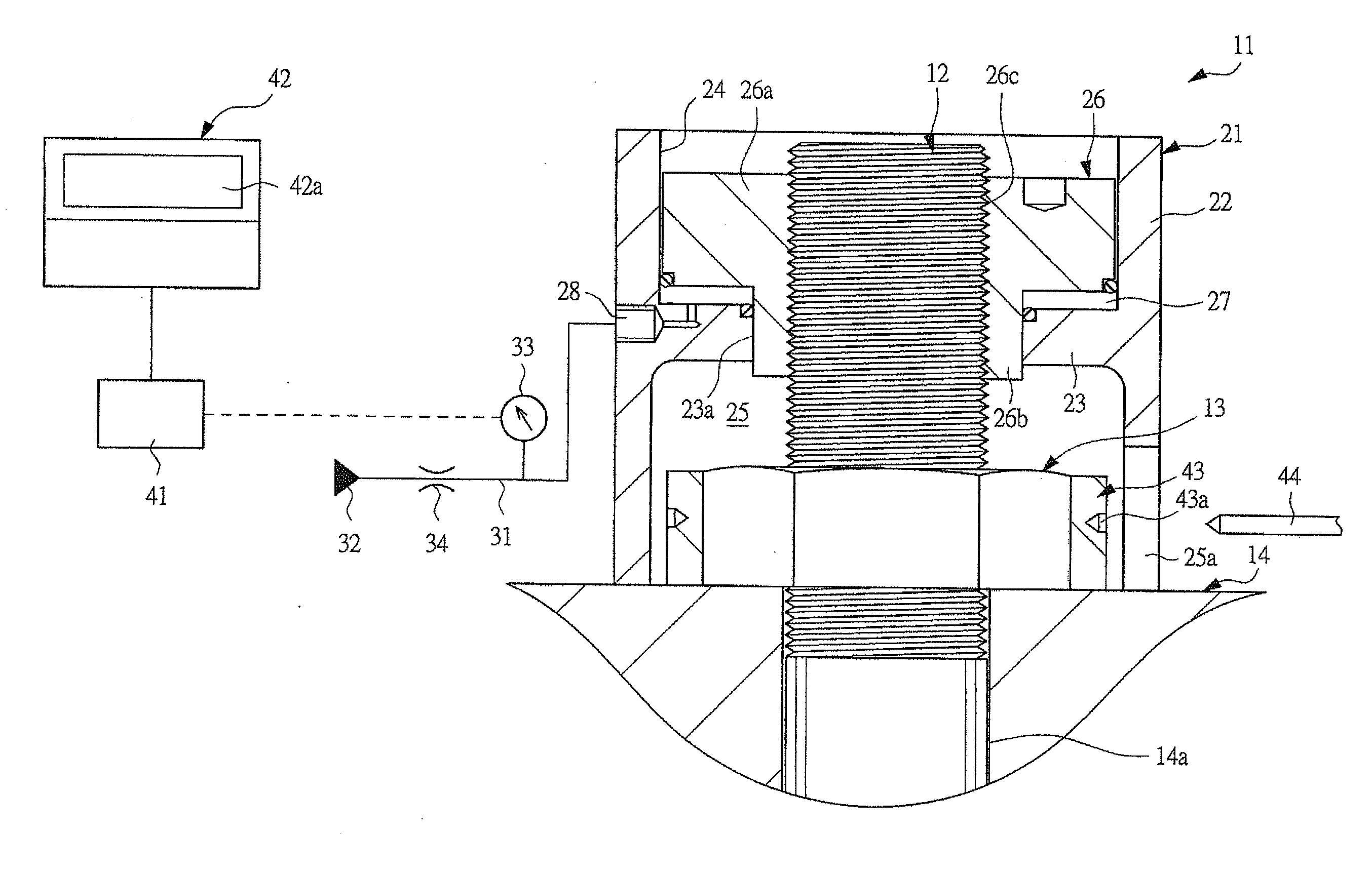
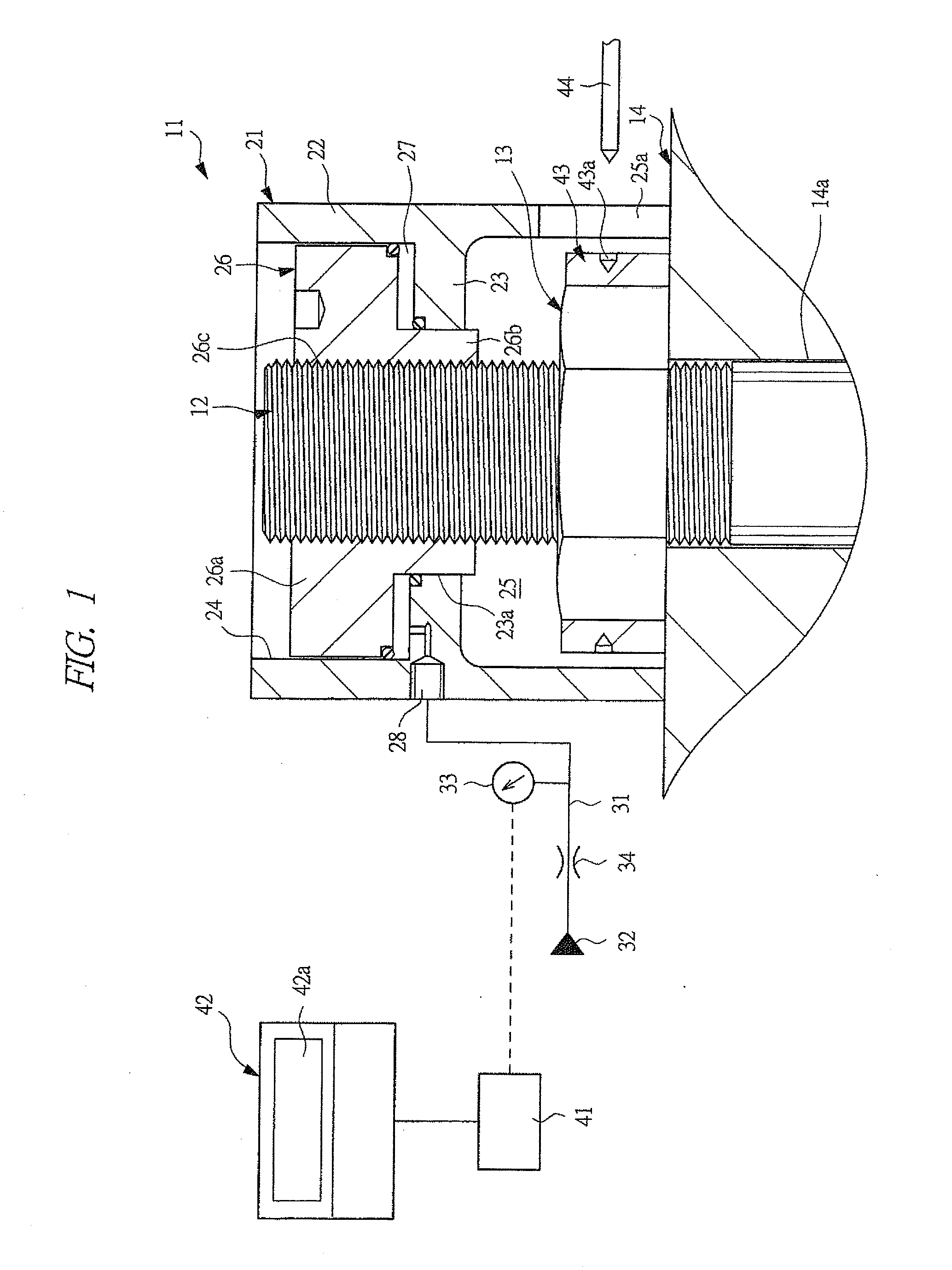
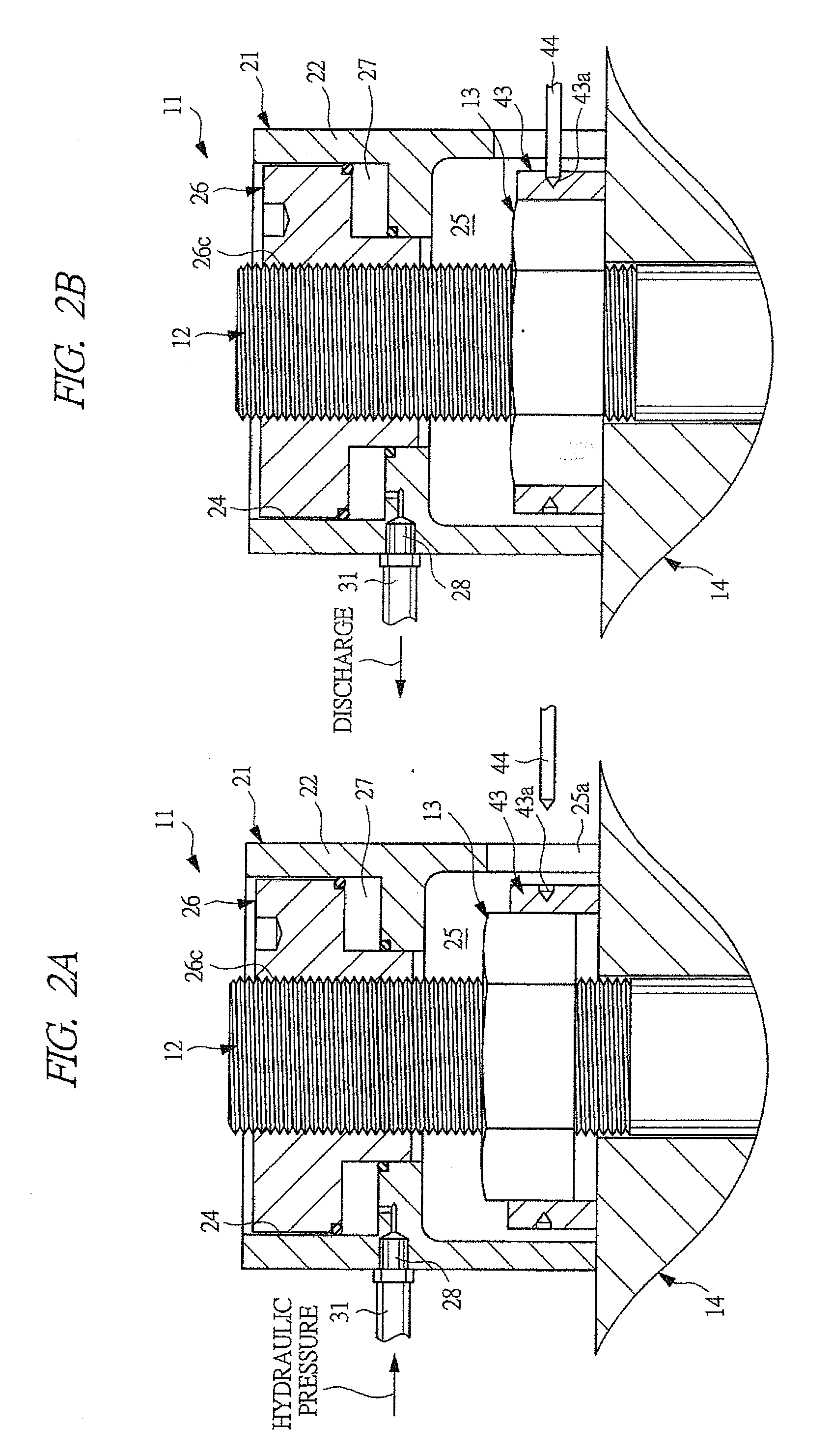
[0041]A bolt-axial-force measuring method according to an embodiment of the present invention is performed by using a bolt-axial-force measuring instrument 11 (hereinafter, referred to as “measuring instrument 11”) shown in FIG. 1.

[0042]This measuring instrument 11 fastens a fastened member 14 with a large fastening force by screw-joining a nut 13 to a bolt 12 in a state in which an axial-directional tensile force is applied in advance to the bolt 12. Simultaneously, during its fastening operation, the measuring instrument 11 measures an axial force of the bolt 12 to be fastened. This measuring method and the measuring instrument 11 are applied, for example, in the cases where: a turbine case of a gas turbine used in a power plant such as an electric power plant is used as the fastened member 14; this fastened member 14 is fastened by the bolt 12 and the nut 13;...


PUM

PropertyMeasurementUnit
frequencyaaaaaaaaaa
axial forceaaaaaaaaaa
tensile forceaaaaaaaaaa

Abstract

A bolt-axial-force measuring method and instrument capable of easily and precisely measuring an axial force of a bolt are provided. The bolt is screw-joined and coupled to a piston of a bolt tensioner, and a hydraulic pressure is supplied to its pressure chamber so that the bolt is elongated by applying a tensile force equal to or more than a necessary bolt-fastening force. A nut separating from a fastened member due to the elongation of the bolt is seated again on the fastened member, and the hydraulic pressure in the pressure chamber is discharged to release the tensile force of the bolt. A pressure change of the pressure chamber from which the hydraulic pressure is discharged is detected by a pressure sensor, a point where a change rate of the pressure change detected by a measuring apparatus is suddenly reduced is detected as an inflection point, and a pressure value of the pressure chamber at the inflection point is multiplied by a pressure receiving area of the pressure chamber, whereby the axial force of the bolt is calculated.

Description

CROSS-REFERENCE TO RELATED APPLICATION[0001]Applicant hereby claims foreign priority benefits under U.S.C. §119 from Japanese Patent Application No. 2010-11680 filed on Jan. 22, 2010, the contents of which are incorporated by reference herein.TECHNICAL FIELD OF THE INVENTION[0002]The present invention relates to a bolt-axial-force measuring method for measuring axial forces (fastening forces) of bolts, which are screw-joined to nuts and fasten members to be fastened (hereinafter “fastened members”), and to a bolt-axial-force measuring instrument used for the measuring method thereof.BACKGROUND OF THE INVENTION[0003]Conventionally, a variety of methods has been used as bolt-axial-force measuring methods for measuring the axial forces of the bolts, which are screw-joined to the nuts and fasten the fastened members.[0004]A load cell method is a method in which: a load cell is sandwiched between an intermediate of a bolt to be fastened or a bolt and a fastened member; under that state, ...

Claims


Application Information

Patent Timeline
Patent Type & Authority Applications(United States)
IPC IPC(8): G06F19/00G01L5/00
CPCG01L5/24
Inventor IMAI, ATSUSHIIMAI, TOORU
Owner IMAI ATSUSHI
Why Eureka
Try Eureka