Housing structure

a technology of housing structure and housing plate, applied in the field of housing plate, can solve the problems of insufficient stability and insufficient self-supporting of the housing plate alone, and achieve the effect of simple and reproducible connection

Inactive Publication Date: 2011-09-08
CARL ZEISS SMT GMBH
View PDF11 Cites 1 Cited by
  • Summary
  • Abstract
  • Description
  • Claims
  • Application Information

AI Technical Summary

Benefits of technology

[0005]The object of the present invention is to avoid the above-named disadvantages of the prior art, in particular to create a housing structure, there being a simpler and reproducible connection between the housing structure and the optical elements arranged therein.
[0008]In addition to a saving of material and weight and of installation space, a clearer and reproducible connection is created in this way between the frame structure and the optical elements. The individual optical elements, which are arranged either individually in a mount, or else in subgroups or in structural modules, can be separately constructed, preadjusted and tested and be installed in the frame structure as appropriately prefabricated units only after this, and be appropriately adjusted in the process.

Problems solved by technology

This means that without the optical elements inserted the housing structure alone is not self-supporting or sufficiently stable, but that an integral load-bearing unit results after installation of the optical elements.

Method used


Image

  • Housing structure
  • Housing structure
  • Housing structure

Examples


Embodiment Construction

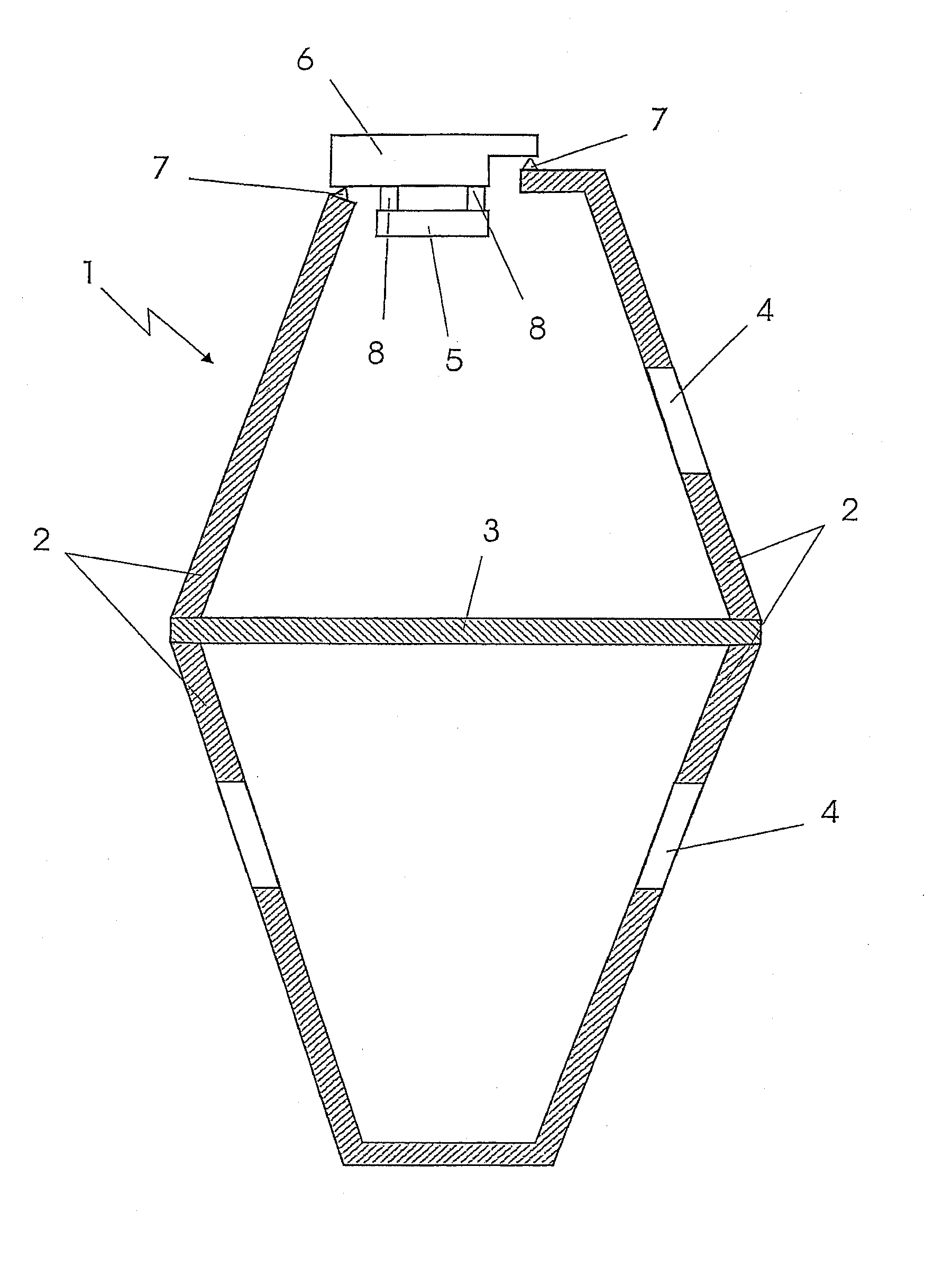
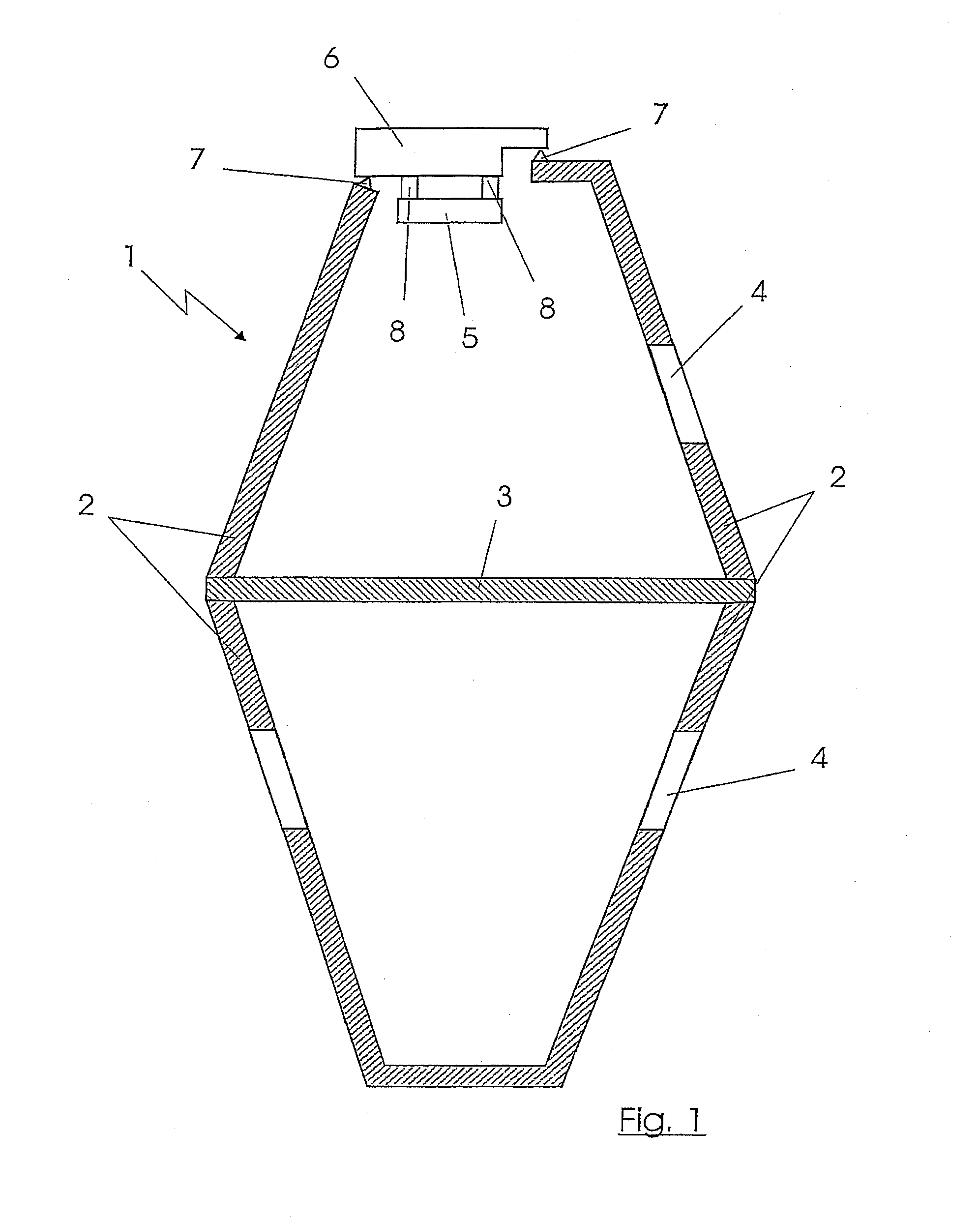
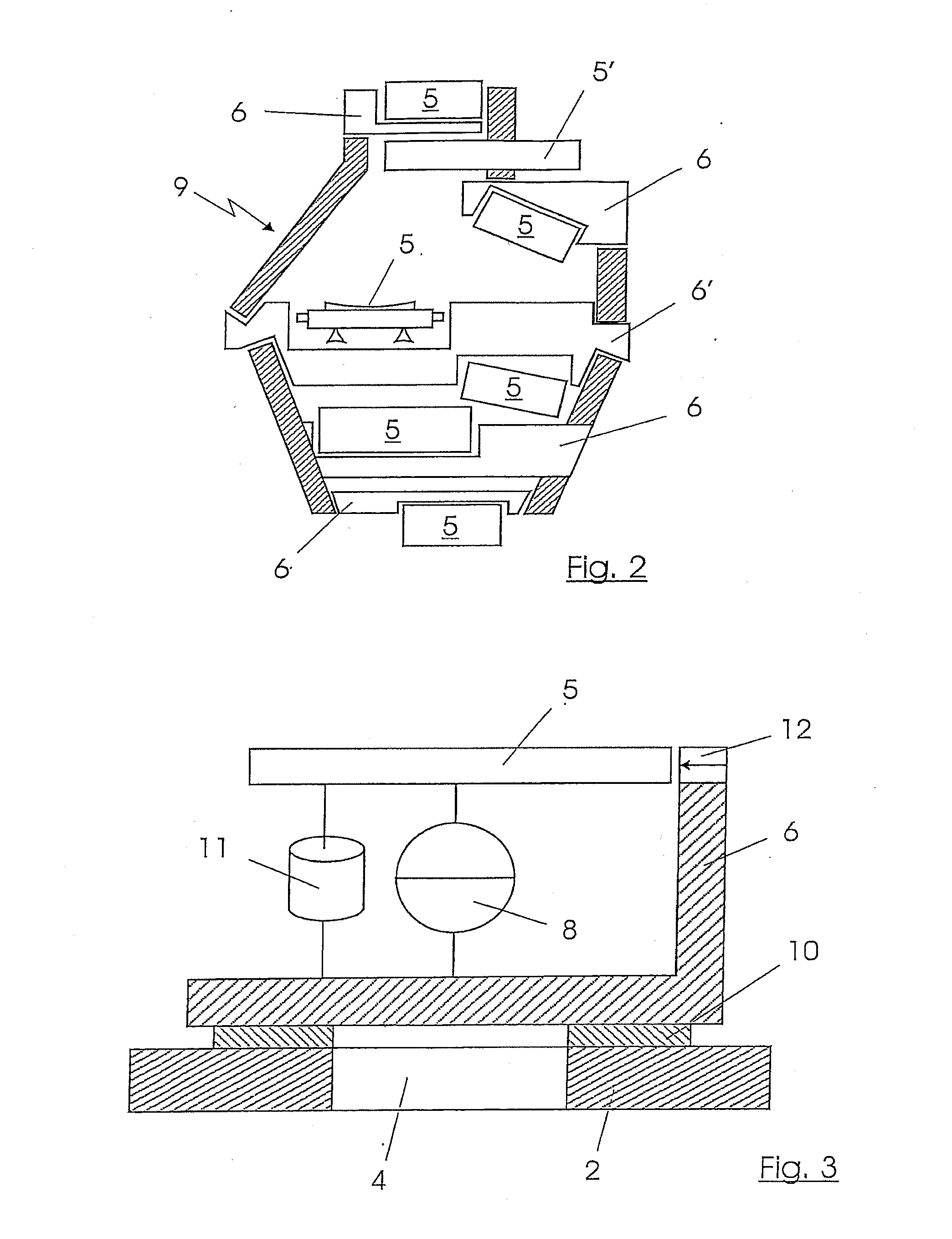
[0016]The housing structure illustrated in FIGS. 1 and 2 has a frame structure 1 which is assembled from several frame parts 2 and reinforcing plates 3. The frame structure 1 is provided with a multiplicity of cutouts or openings 4. Optical elements 5 with their mounts 6 are inserted into the openings 4. Connecting elements 7 (not illustrated in more detail) are provided for this purpose. Setting members or actuators 8 are arranged between the mount 6, which can be constructed as a base element, and the optical element 5, for example, a mirror 5. The arrangement and configuration of the setting members 8 are not described in more detail below, since they are known in principle. The setting members 8 should as far as possible permit adjustments of the optical element 5 in six degrees of freedom, and can be constructed for this purpose as hexapods, for example.

[0017]FIG. 2 shows a housing structure which can be, for example, an objective housing 9 of a projection objective in microlit...


PUM

PropertyMeasurementUnit
degrees of freedomaaaaaaaaaa
coefficient of thermal expansionaaaaaaaaaa
degrees of freedomaaaaaaaaaa

Abstract

A housing structure has a frame structure 1 on which there are arranged via connecting elements 7 several optical elements 5 which are held in mounts 6 or structural modules 6′. The optical elements 5 are detachably connected to the frame structure 1 with their mounts 6 or structural modules 6′ and connecting elements 7 in such a way that in the installed state they are integrated as bearing units in the frame structure 1.

Description

BACKGROUND OF THE INVENTION[0001]1. Field of the Invention[0002]The invention relates to a housing structure which has a frame structure on which there are arranged via connecting elements several optical elements which are held in mounts or structural modules.[0003]2. Description of the Prior Mt[0004]A housing structure of this type is described, for example, in EP 1 278 089 A2. It has frame parts and connecting plates on which several optical elements are fastened, bores or openings being provided in part for this purpose. The housing structure forms a stable self-supporting unit. Appropriate auxiliary constructions with fastening elements are required for fastening the optical elements with their mounts or structural modules. The mounting is relatively complicated, and an additional installation space is required for the connection. The optical elements connected to the frame structure constitute virtually separate parts on the housing structure and have little dynamic influence ...

Claims


Application Information

Patent Timeline
Patent Type & Authority Applications(United States)
IPC IPC(8): G02B7/182G01M11/04G02B7/00G03F7/20
CPCG01M11/04G02B7/00G03F7/70825G03F7/70808G02B7/182
Inventor XALTER, STEFANDEUFEL, PETERKWAN, YIM BUN PATRICKSTOMMEN, BERNARDSOEMERS, HERMANVAN DEUREN, FRANZBROM, PAUL PETER ANNE
Owner CARL ZEISS SMT GMBH
Why Eureka
Try Eureka