
Automatically Steered Gearboxes for an Implement with a Pivoting Tongue

a technology of automatic steering and gearboxes, which is applied in the direction of transportation and packaging, agriculture tools and machines, agriculture, etc., can solve the problems of the delivery of driving power from the tractor to the operating components of the machin

Active Publication Date: 2011-09-15
VERMEER MFG CO
View PDF25 Cites 11 Cited by
  • Summary
  • Abstract
  • Description
  • Claims
  • Application Information

AI Technical Summary

Benefits of technology

[0014]One aspect of the present invention is the arrangement of the tongue and the driveline with a swivel gear box assembly, the combination of gearboxes one and two, mounted at the front portion of the tong

Problems solved by technology

However, having a pulling tongue which is shifted between relatively sharp angular positions create

Method used


Image

  • Automatically Steered Gearboxes for an Implement with a Pivoting Tongue
  • Automatically Steered Gearboxes for an Implement with a Pivoting Tongue
  • Automatically Steered Gearboxes for an Implement with a Pivoting Tongue

Examples


embodiment 100

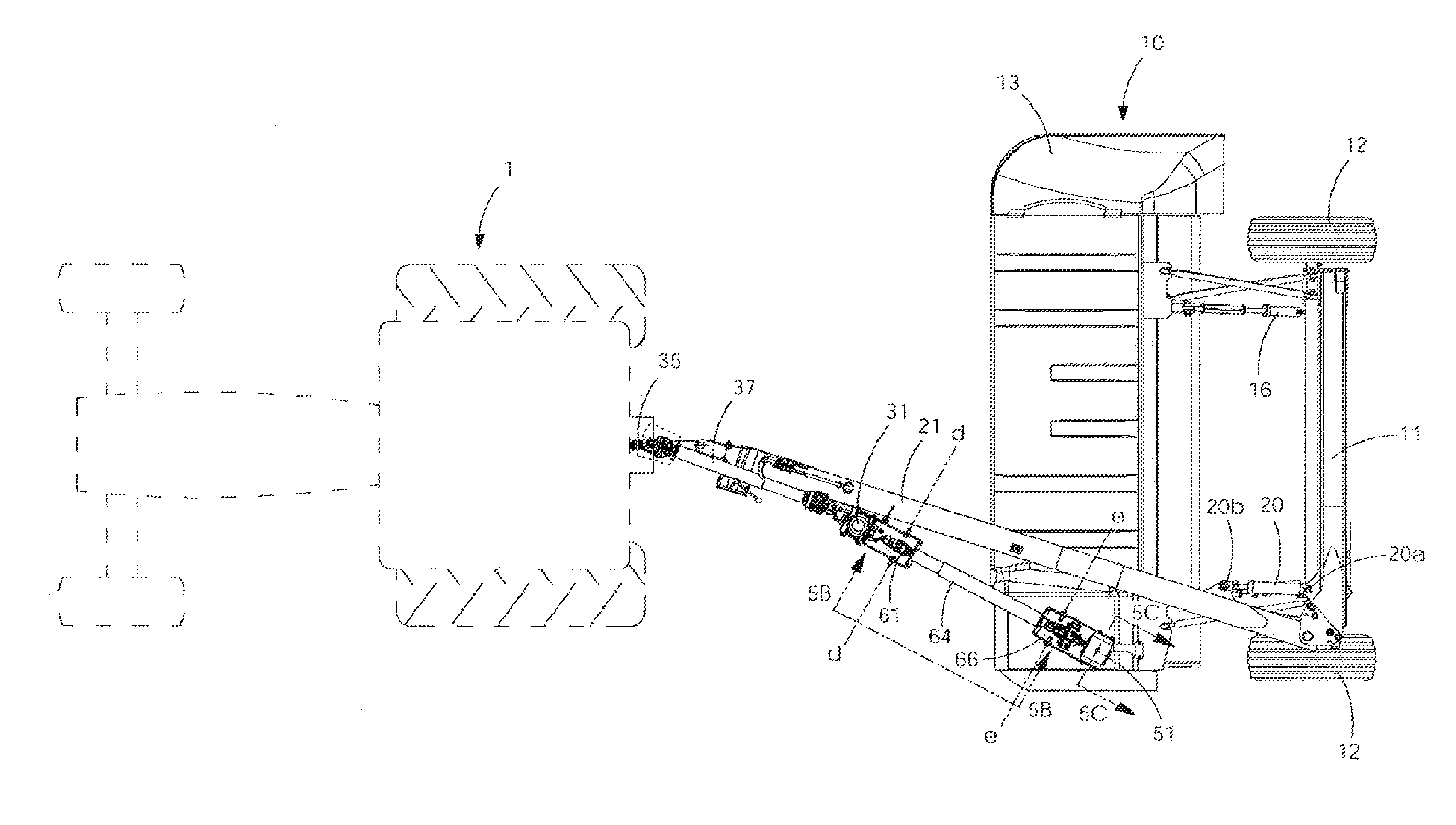
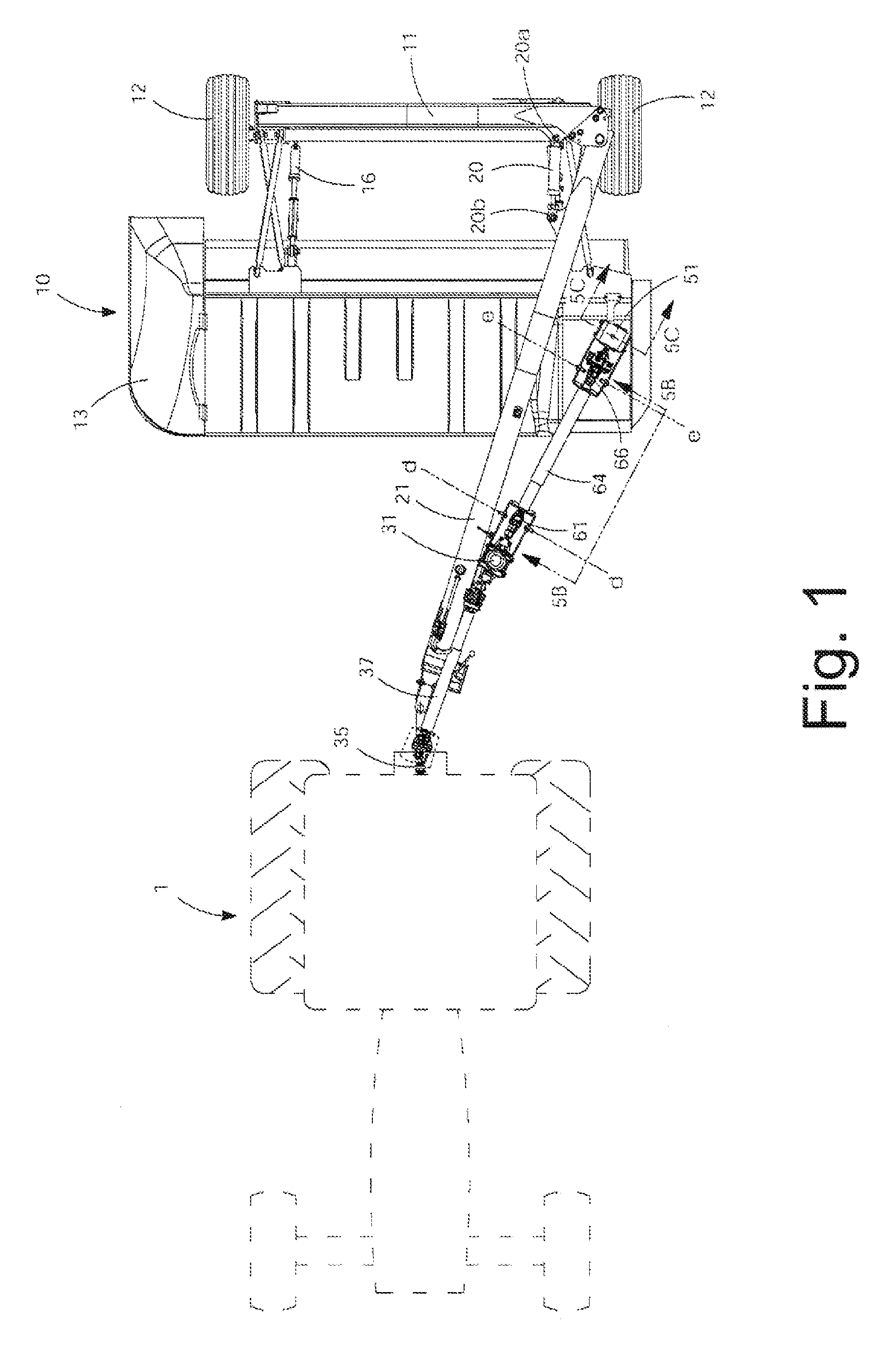
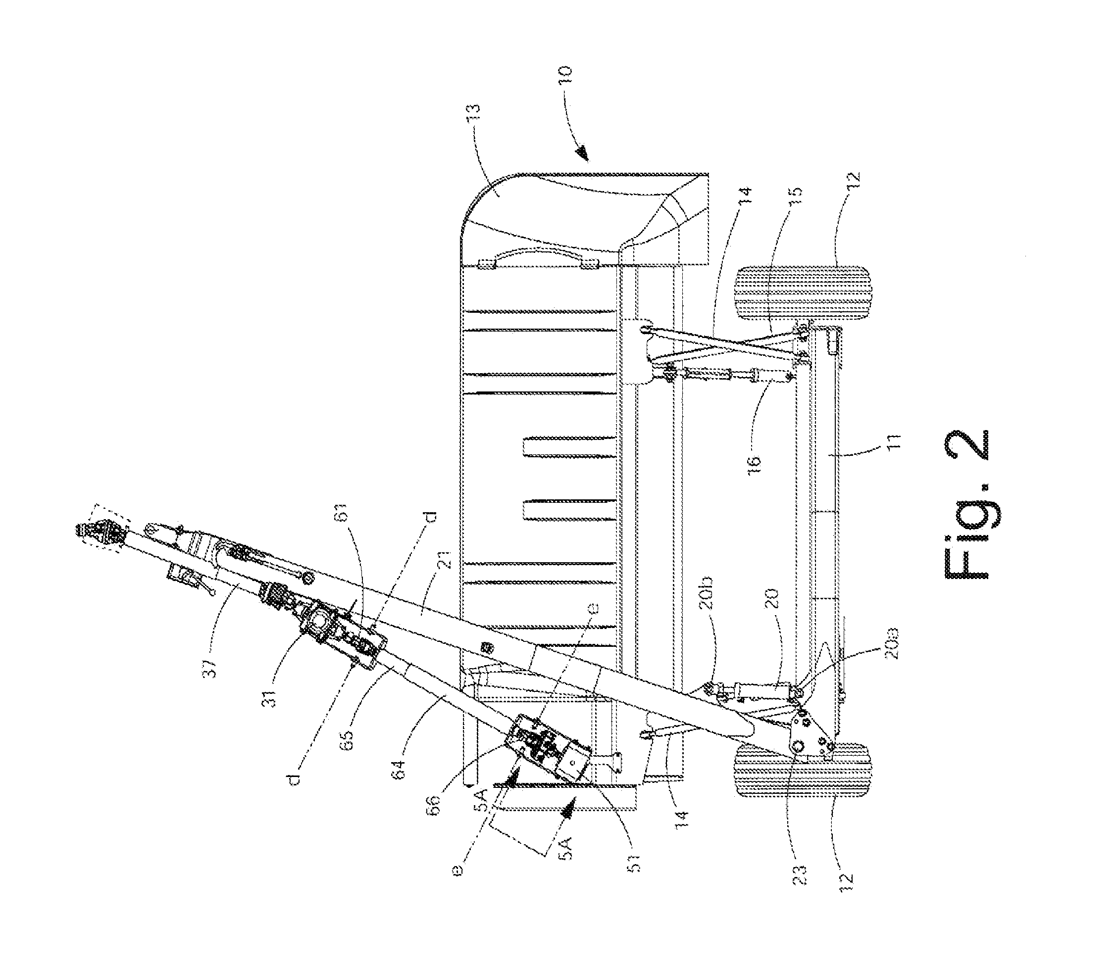
[0052]Referring now to an alternate embodiment 100 in FIGS. 13,14 and 15, the front gearboxes (31) and (41) of the FIGS. 1-12 embodiment are replaced with a normal increaser front gearbox (131) with an input shaft (133) for attachment to the drive shaft (37) via a u-joint as in FIG. 1, the input shaft (133) being disposed along a rotational axis (f) and an output shaft (136) that is disposed along a rotational axis (g) that is preferably parallel to the rotational axis (f) but is not required to be parallel to the axis (f).

second embodiment

[0053]The rear gear box (51) and everything shown in FIGS. 5a and 5c are still the same on this alternate embodiment (100). U-joints (61) and (66) can still be used for example. This alternate embodiment (100) of FIGS. 13 and 14 is steered by a telescoping link (168) with a first member (164) having a spherical ball joint (166) on one end thereof mounted to the top of the front gearbox (131) and a second telescoping member (165) that the first member (164) extends into. This is a similar to the setup of the FIGS. 1-12 embodiment except the spherical ball joint (166) is attached to the front gearbox (131) instead of using the telescoping steering members (64) and (65) shown in FIGS. 1-7. This can optionally eliminate the need for a CV u-joint for the rear gearbox (51) and the front one (61) is not as critical so a standard u-joint could be used there. The same telescoping drive linkage (62), including receiver (62a) having complementary shaft (62b) extending therein as shown in FIG. ...


PUM


Abstract

A mower is suspended from a frame and includes a header with a cutter. A tongue is pivotally connected to the mower frame and is moveable with respect to the frame by a hydraulic cylinder. At the front of the tongue is a front gearbox rigidly attached to the tongue. The front gearbox transmits rotary power from the power take off of the tractor to a rear gearbox pivotally attached the header and from the rear gearbox rotary power is passed on ultimately to the rotary cutting units. Pivoting of the rear gearbox is controlled by a steering connection operatively attached between the front and rear gearboxes.

Description

CROSS-REFERENCE TO RELATED APPLICATIONS[0001]This application claims the benefit of U.S. Provisional Patent Application Ser. No. 61 / 313,419 filed Mar. 12, 2010 entitled “Automatically Steered Gearboxes for a Mower with a Pivoting Tongue” which is incorporated by reference herein in its entirety.STATEMENT REGARDING FEDERALLY SPONSORED RESEARCH OR DEVELOPMENT[0002]Not ApplicableBACKGROUND OF THE INVENTION[0003]1. Field of the Invention[0004]The present invention relates to crop harvesting equipment and, more particularly, to pull-type mowers or mower / conditioners having a pulling tongue which is hydraulically swingable from side-to-side so that the lateral position of the machine relative to the towing tractor can be adjusted on-the-go from the tractor seat. More particularly, the present invention involves a swing tongue harvester of the aforementioned type wherein provision is made for driving the operating components of the harvesting header, such as the crop severing mechanism and...

Claims


Application Information

Patent Timeline
IPC IPC(8): A01D69/06A01D34/01A01D82/00
CPCA01D67/005A01D34/661
Inventor THOMPSON, KENT L.
Owner VERMEER MFG CO
Features
  • Generate Ideas
  • Intellectual Property
  • Life Sciences
  • Materials
  • Tech Scout
  • Unparalleled Data Quality
  • Higher Quality Content
  • 60% Fewer Hallucinations
Learn More