Eureka AIR delivers breakthrough ideas for toughest innovation challenges, trusted by R&D personnel around the world.

Keyboard illumination apparatus and method

Active Publication Date: 2011-09-15
HEWLETT PACKARD DEV CO LP
View PDF11 Cites 3 Cited by
  • Summary
  • Abstract
  • Description
  • Claims
  • Application Information

AI Technical Summary

Benefits of technology

[0007]An interface apparatus is provided. The interface can include a keyboard containing one or more keys, each having a key base and a key top. A light guide having an edge, a first surface and a second surface can be disposed proximate the base of all or a portion of the plurality of keys. The light guide can have a plurality of apertures disposed therethrough, with each aperture corresponding to the location of each of the one or more keys. One or more dispersion features can be disposed in, on, or about each of the one or more apertures to transmit, reflect, or otherwise direct at least a portion of the light transmitted through the light guide in an upward direction into each key base, thereby illuminating the one or more keys.
[0008]The interface can include a keyboard containing a plurality of keys, each key having a key base and a key top. The user interface can further include a light guide having one or more edges, a first surface and a second surface. The first surface of the light guide can disposed about the base of all or a portion of the plurality of keys. The light guide can have a plurality of apertures disposed therethrough, with each aperture forming the plurality of apertures corresponding to the location one or more keys forming the plurality of keys. One or more interior surfaces of each aperture can have one or more fea

Problems solved by technology

Conventional keyboards, while satisfactory in high ambient light conditions, can be difficult to see, read, and / or use in low ambient light conditions.
External illumination however is inefficient as a large portion of the light is lost to the surrounding environment, thereby requiring the use of larger and / or brighter lamps.
Backlighting of keyboards using multiple light sources can result in uneven illumination of the keyboard unless some means to evenly distribute the light is provided.

Method used


Image

  • Keyboard illumination apparatus and method
  • Keyboard illumination apparatus and method
  • Keyboard illumination apparatus and method

Examples


Embodiment Construction

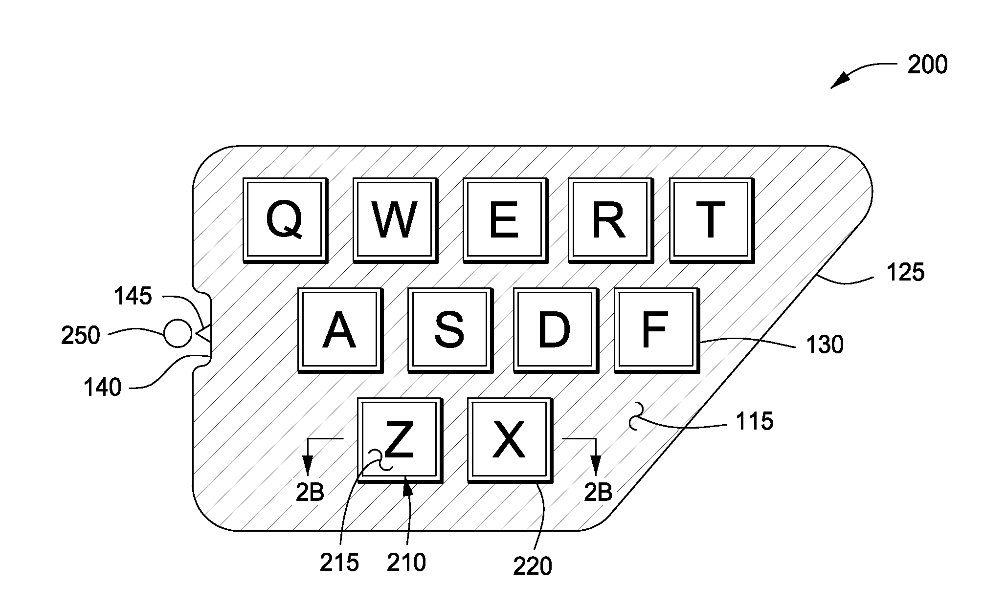
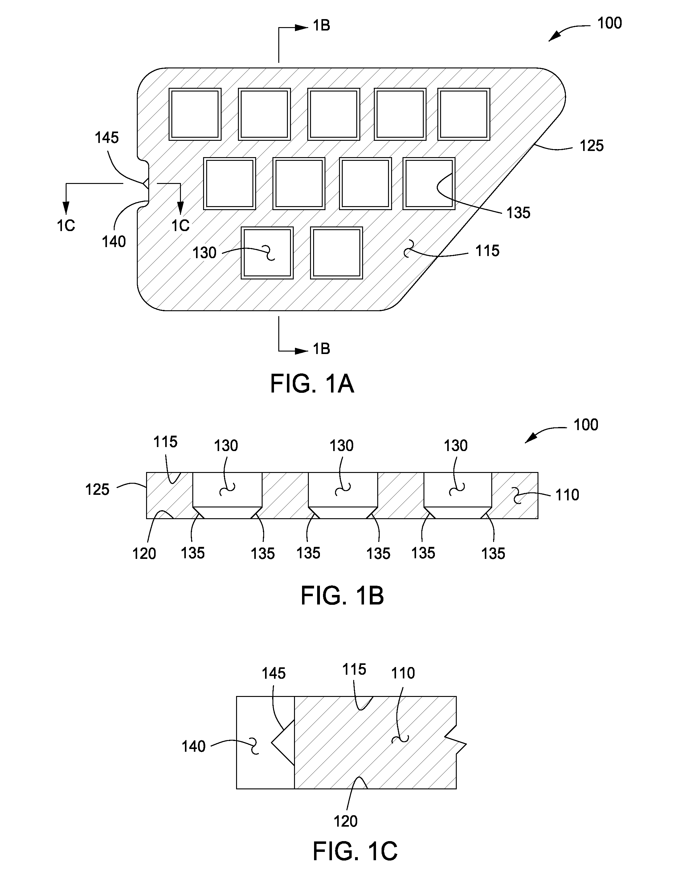
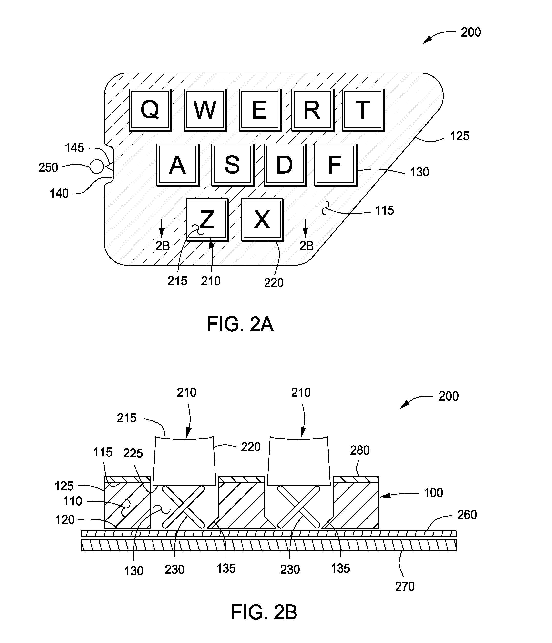
[0018]FIG. 1A depicts a plan view of an illustrative apparatus 100 for illuminating a user interface device, according to one or more embodiments. FIG. 1B depicts a cross-sectional view of the illustrative apparatus depicted in FIG. 1A, along sectional line 1B-1B, according to one or more embodiments. One or more features hidden in FIG. 1A are more clearly depicted in FIG. 1B. FIG. 1C depicts a cross-sectional view of the illustrative apparatus depicted in FIG. 1A, along sectional line 1C-1C, according to one or more embodiments. One or more features hidden in FIG. 1A are more clearly depicted in FIG. 1C. In one or more embodiments, the illustrative apparatus 100 can include a light guide 110 having a first (“upper”) surface 115, a second (“lower”) surface (not shown in FIG. 1A) 120, and at least one edge 125. One or more apertures 130 can be disposed in, on, or about the light guide 110. In one or more embodiments, the one or more apertures can extend partially or completely betwee...


PUM


Abstract

Interface apparatus and methods are provided. The interface can include a keyboard (200) containing one or more keys (210), each having a key base and a key top. A light guide (110) having an edge (125), a first surface (115) and a second surface (120) can be disposed proximate the base of all or a portion of the plurality of keys. The light guide can have a plurality of apertures (130) disposed therethrough, with each aperture corresponding to the location of each of the one or more keys. One or more dispersion features (135) can be disposed in, on, or about each of the one or more apertures to transmit at least a portion of the light from the light guide to the base of each key.

Description

BACKGROUND OF THE INVENTION[0001]1. Field of the Invention[0002]Embodiments of the present invention generally relate to keyboards used on electronic devices. More particularly, embodiments of the present invention relate to the apparatus and methods for illuminating keyboards used on electronic devices.[0003]2. Description of the Related Art[0004]Many electronic devices use numeric or alphanumeric keyboards for user entry of data into the device, i.e. an input device. While desktop and other stationary electronic devices are frequently used only in high ambient light environments, mobile devices such as cellular telephones, portable computers, and personal data assistants are often used in low ambient light environments. Conventional keyboards, while satisfactory in high ambient light conditions, can be difficult to see, read, and / or use in low ambient light conditions.[0005]Various techniques have been used to illuminate keyboards on electronic devices. One option is to illuminate...

Claims


Application Information

Patent Timeline
IPC IPC(8): H03M11/00
CPCG06F3/0202G02B6/0016G06F3/02
Inventor SELLERS, CHARLES A.
Owner HEWLETT PACKARD DEV CO LP
Why Eureka
Eureka Blog
Learn More