Spark ignition device for an internal combustion engine, metal shell therefor and methods of construction thereof

a technology of spark ignition and internal combustion engine, which is applied in the manufacture of sparking plugs, sparking plugs, electrical equipment, etc., can solve the problems of lack of joint strength, increase in temperature of burning atmosphere in the engine, and separation of ground electrode from metal shell, so as to facilitate repeatable and accurate positioning of ground electrodes and improve heat transfer paths

Active Publication Date: 2011-10-06
FEDERAL MOGUL IGNITION
View PDF2 Cites 6 Cited by
  • Summary
  • Abstract
  • Description
  • Claims
  • Application Information

AI Technical Summary

Benefits of technology

[0009]According to one aspect of the invention, a spark ignition device is provided. The spark ignition device has a generally annular ceramic insulator extending along a longitudinal axis and a metal shell surrounding at least a portion of the ceramic insulator. The metal shell extends along the longitudinal axis between a proximal end and a distal end. A center electrode is received at least in part in the ceramic insulator and extends coaxially along the longitudinal central axis. A ground electrode has an attachment end fixed by a weld joint to the distal end of the shell and a free end extending from the distal end to provide a spark gap between the center electrode and the ground electrode. The weld joint includes a resistance weld joint and a laser weld joint, which in combination inhibit material expulsion; provide a reliable, strong attachment of the ground electrode to the shell; provide an improved heat transfer path between the ground electrode and the shell, and facilitate repeatable and accurate positioning of the ground electrode to the shell.

Problems solved by technology

Modern automotive vehicles are required to meet increased power, low fuel consumption, and low exhaust emissions requirements, thus resulting in an increase in temperature of burning atmosphere in the engine.
Therefore, weld joints between a metal shell of a spark ignition device and a ground electrode are subjected to increased temperatures, and thus, have become more prone to cracking, thus resulting in separation of the ground electrode from the metal shell.
When the ground electrode is joined to the metal shell using typical laser welding techniques, a weld joint formed between them is usually small, which could result in a lack of the strength of the joint.
As such, secondary, inefficient and costly manufacturing operations are needed to “clean-up” the expelled material.
Further yet, if the laser weld joint is formed with a gap or voids existing and remaining between the ground electrode and the shell, the laser weld joint can be subject to premature failure.
However, a weld joint formed solely by a resistance weld process generally requires the ground electrode to be upset, i.e. pushed into the material of the shell while high current flows, thereby causing material of the ground electrode and the metal shell to be expelled as discussed above, thus requiring secondary, inefficient and costly manufacturing operations to “clean-up” the expelled material.
Further, a resistance weld joint is formed primarily as a “forge weld”, which produces limited fused material in the weld joint, thus lending to a weld joint that has relatively low strength.

Method used


Image

  • Spark ignition device for an internal combustion engine, metal shell therefor and methods of construction thereof
  • Spark ignition device for an internal combustion engine, metal shell therefor and methods of construction thereof
  • Spark ignition device for an internal combustion engine, metal shell therefor and methods of construction thereof

Examples


Embodiment Construction

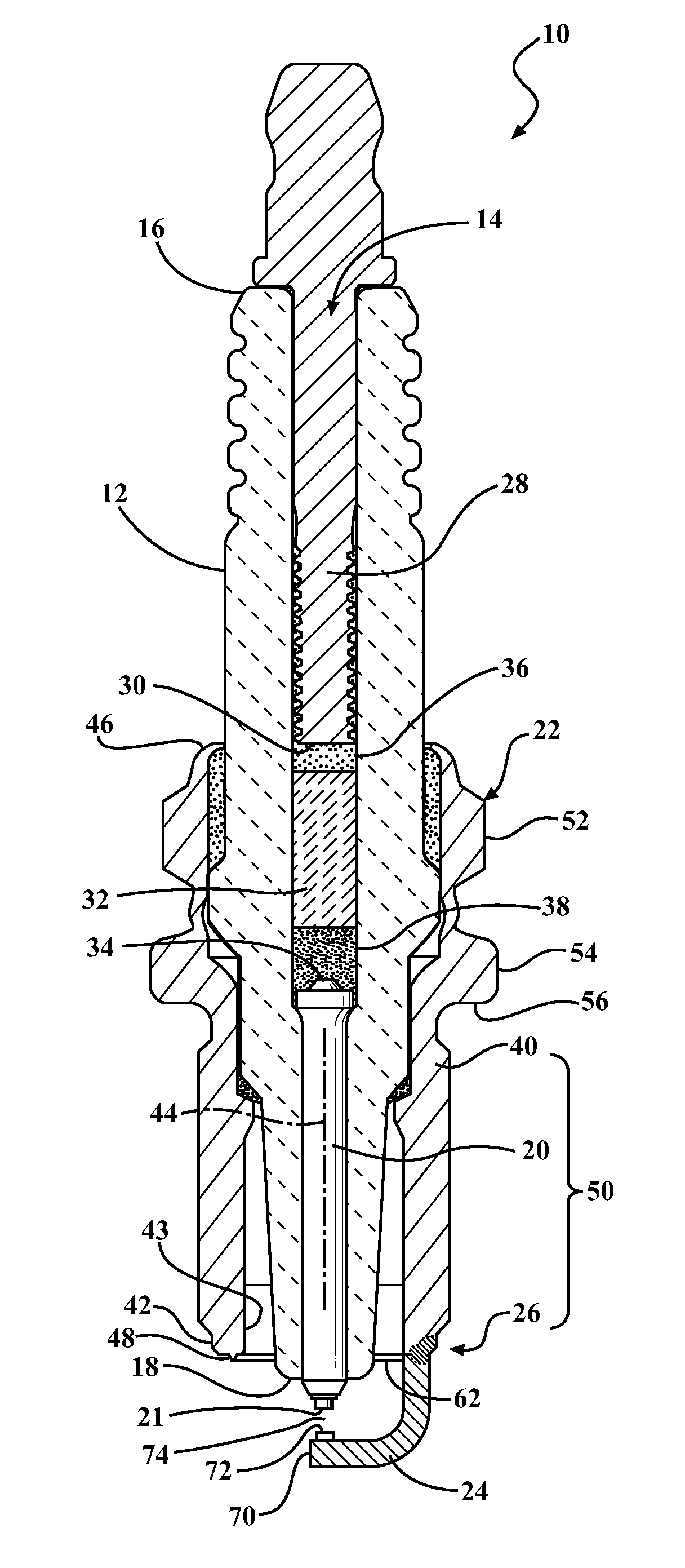
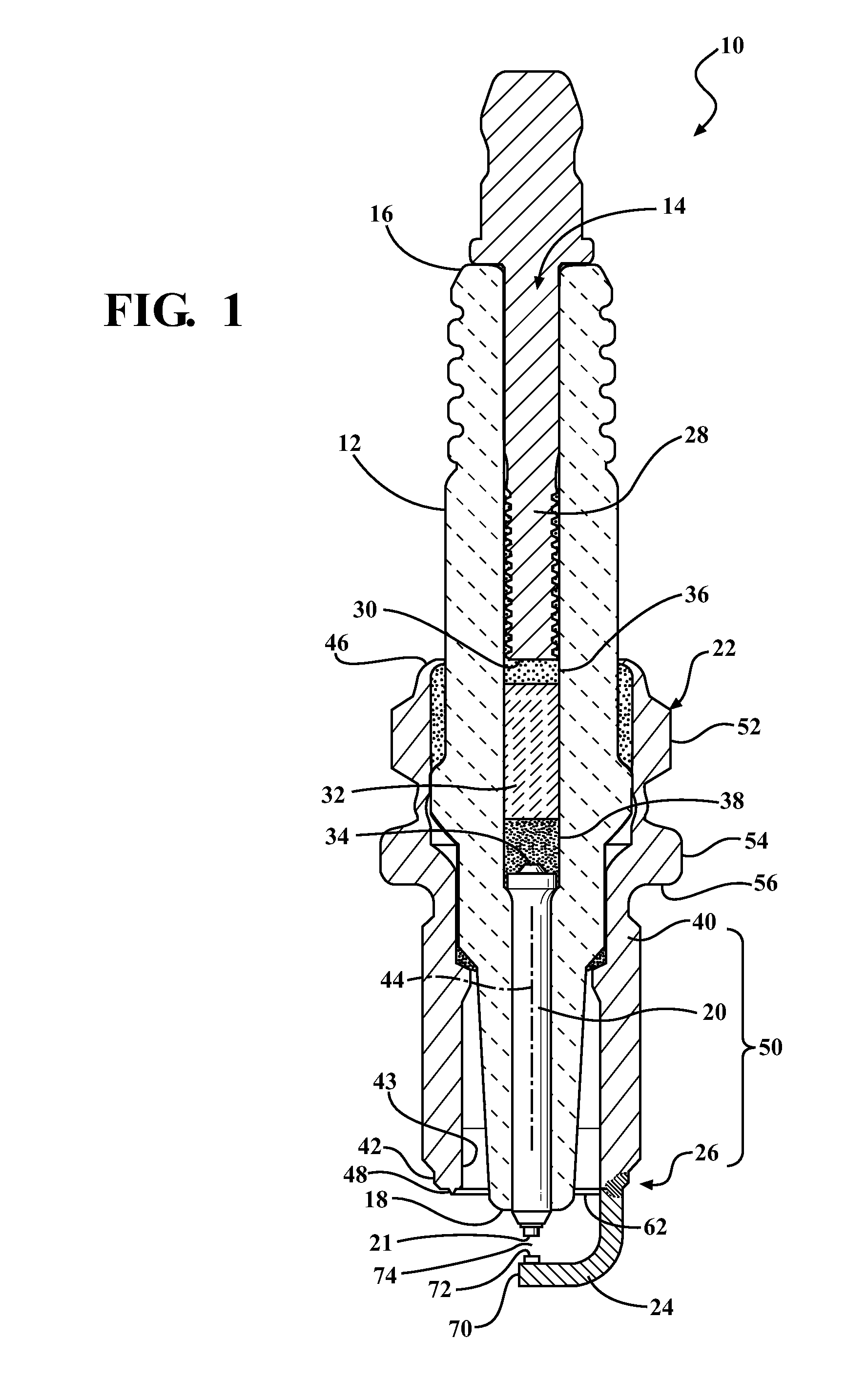
[0022]Referring in more detail to the drawings, FIG. 1 illustrates a spark ignition device 10 constructed in accordance with one presently preferred aspect of the invention for use in igniting a fuel / air mixture in internal combustion engines. The exemplary spark ignition device 10 is illustrated in the form of a spark plug that includes, among other things, an annular ceramic insulator 12 fabricated of aluminum oxide or another suitable electrically insulating material in known manner. The insulator 12 has a central passage 14 extending longitudinally between an upper terminal end 16 and a lower nose or core end 18 in which a center electrode 20 is disposed. The center electrode 20 has a sparking surface, referred to hereafter as sparking tip 21, at a free end thereof. An electrically conductive metal shell 22 is disposed in sealed relation about the lower and mid portions of the insulator 12 and may be made from any suitable metal, such as various steel alloys, and may be coated w...


PUM


Abstract

A spark ignition device, metal shell, and methods of construction are provided. The spark ignition device has a ceramic insulator extending along a longitudinal axis and a metal shell. The metal shell extends along the longitudinal axis to a distal end. A center electrode is received in the ceramic insulator and extends along the longitudinal axis. A ground electrode has an attachment end fixed by a weld joint to the distal end of the shell and a free end extending from the distal end to provide a spark gap. The weld joint includes a resistance weld joint and a laser weld joint, which in combination inhibit material expulsion; provide a reliable, strong attachment of the ground electrode to the shell; provide an improved heat transfer path between the ground electrode and the shell, and facilitate repeatable and accurate positioning of the ground electrode to the shell.

Description

BACKGROUND OF THE INVENTION[0001]1. Technical Field[0002]This invention relates generally to spark ignition devices, such as spark plugs for internal combustion engines, and more particularly to ground electrodes attached to a metal shell of the spark ignition device and to their method of attachment to the metal shell.[0003]2. Related Art[0004]Modern automotive vehicles are required to meet increased power, low fuel consumption, and low exhaust emissions requirements, thus resulting in an increase in temperature of burning atmosphere in the engine. Therefore, weld joints between a metal shell of a spark ignition device and a ground electrode are subjected to increased temperatures, and thus, have become more prone to cracking, thus resulting in separation of the ground electrode from the metal shell.[0005]When the ground electrode is joined to the metal shell using typical laser welding techniques, a weld joint formed between them is usually small, which could result in a lack of t...

Claims


Application Information

Patent Timeline
Patent Type & Authority Applications(United States)
IPC IPC(8): H01T13/20H01T21/02
CPCH01T21/02H01T13/32
Inventor QUITMEYER, FREDERICK J.
Owner FEDERAL MOGUL IGNITION
Why Eureka
Try Eureka