LED lamp with remote phosphor and diffuser configuration

Active Publication Date: 2011-11-03
IDEAL IND LIGHTING LLC
View PDF24 Cites 43 Cited by
  • Summary
  • Abstract
  • Description
  • Claims
  • Application Information

AI Technical Summary

Benefits of technology

[0015]The present invention provides lamps and bulbs generally comprising different combinations and arrangement of a light source, one or more wavelength conversion materials, regions or layers which are positioned separately or remotely with respect to the light source, and a separate diffusing layer. This arrangement allows for the fabrication of lamps and bulbs that are efficient, reliable and cost effective and can provide an essentially omnidirectional emission pattern, even with a light source comprised of a co-planar arrangement of LEDs. Additionally, this arrangement allows aesthetic masking or concealment of the appearance of the conversion regions or layers when the lamp is not illuminated. Various embodiments of the invention may be used to address many of the difficulties associat

Problems solved by technology

However, such lamps are highly inefficient light sources, with as much as 95% of the input energy lost, primarily in the form of heat or infrared energy.
One common alternative to incandescent lamps, so-called compact fluorescent lamps (CFLs), are more effective at converting electricity into light but require the use of toxic materials which, along with its various compounds, can cause both chronic and acute poisoning and can lead to environmental pollution.
While the reflective cup 13 may direct light in an upward direction, optical losses may occur when the light is reflected (i.e. some light may be absorbed by the reflective cup due to the less than 100% reflectivity of practical reflector surfaces).
In addition, heat retention may be an issue for a package such as the package 10 shown in FIG. 1a, since it may be difficult to extract heat through the leads 15A, 15B.
LED chips which have a conversion material in close proximity or as a direct coating have been used in a variety of different packages, but experience some limitations based on the structure of the devices.
Further, in such cases the phosphor can be subjected to very high concentrations or flux of incident light from the LED.
Since the conversion process is in general not 100% efficient, excess heat is produced in the phosphor layer in proportion to the incident light flux.
In compact phosphor layers close to the LED chip, this can lead to substantial temperature increases in the phosphor layer as large quantities of heat are generated in small areas.
This temperature increase can be exacerbated when phosphor particles are embedded in low thermal conductivity material such as silicone which does not provide an effective dissipation path for the heat generated within the phosphor particles.
Such elevated operating temperatures can cause degradation of the phosphor and surrounding materials over time, as well as a reduction in phosphor conversion efficiency and a shift in conversi

Method used


Image

  • LED lamp with remote phosphor and diffuser configuration
  • LED lamp with remote phosphor and diffuser configuration
  • LED lamp with remote phosphor and diffuser configuration

Examples


Embodiment Construction

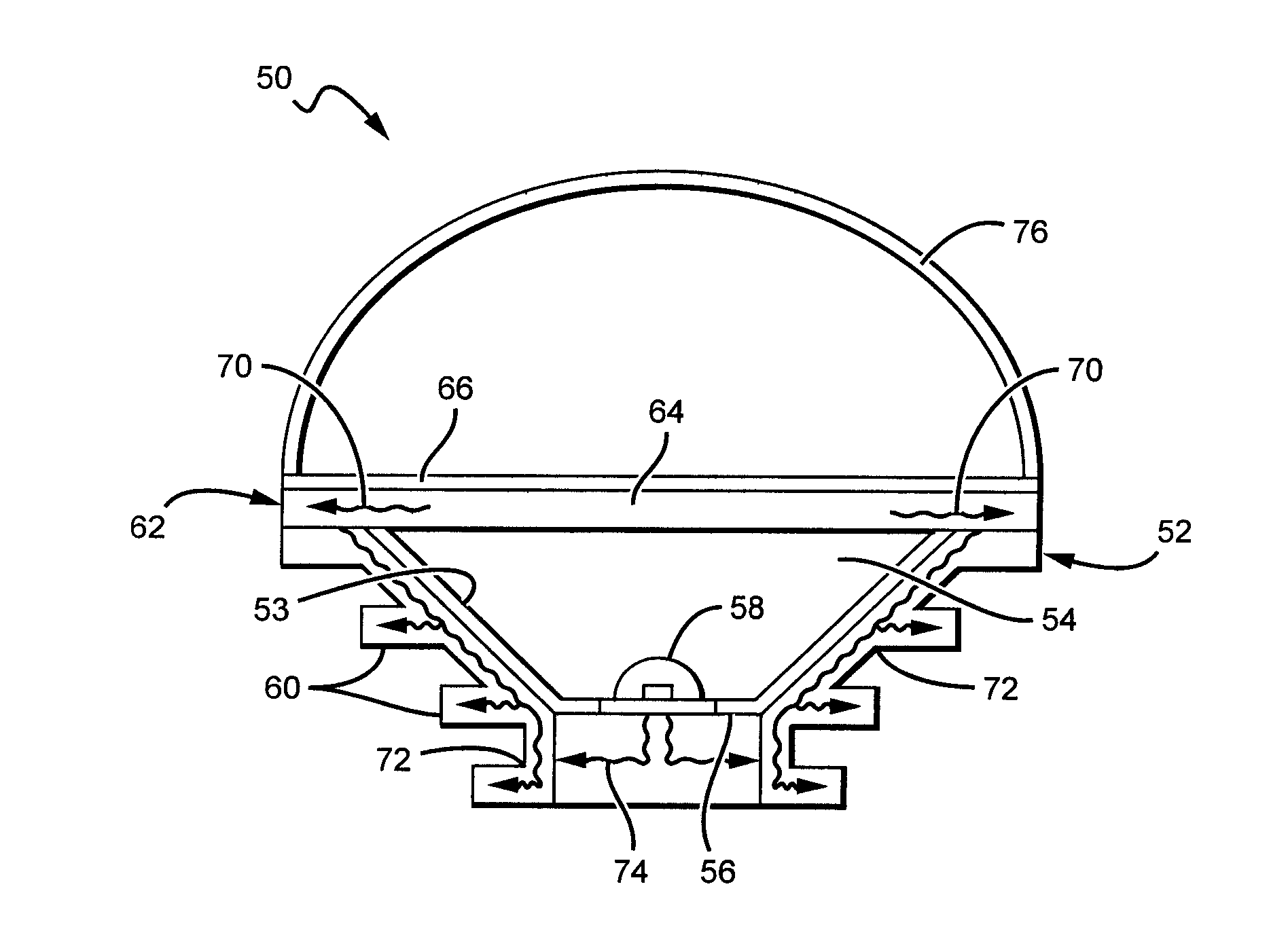
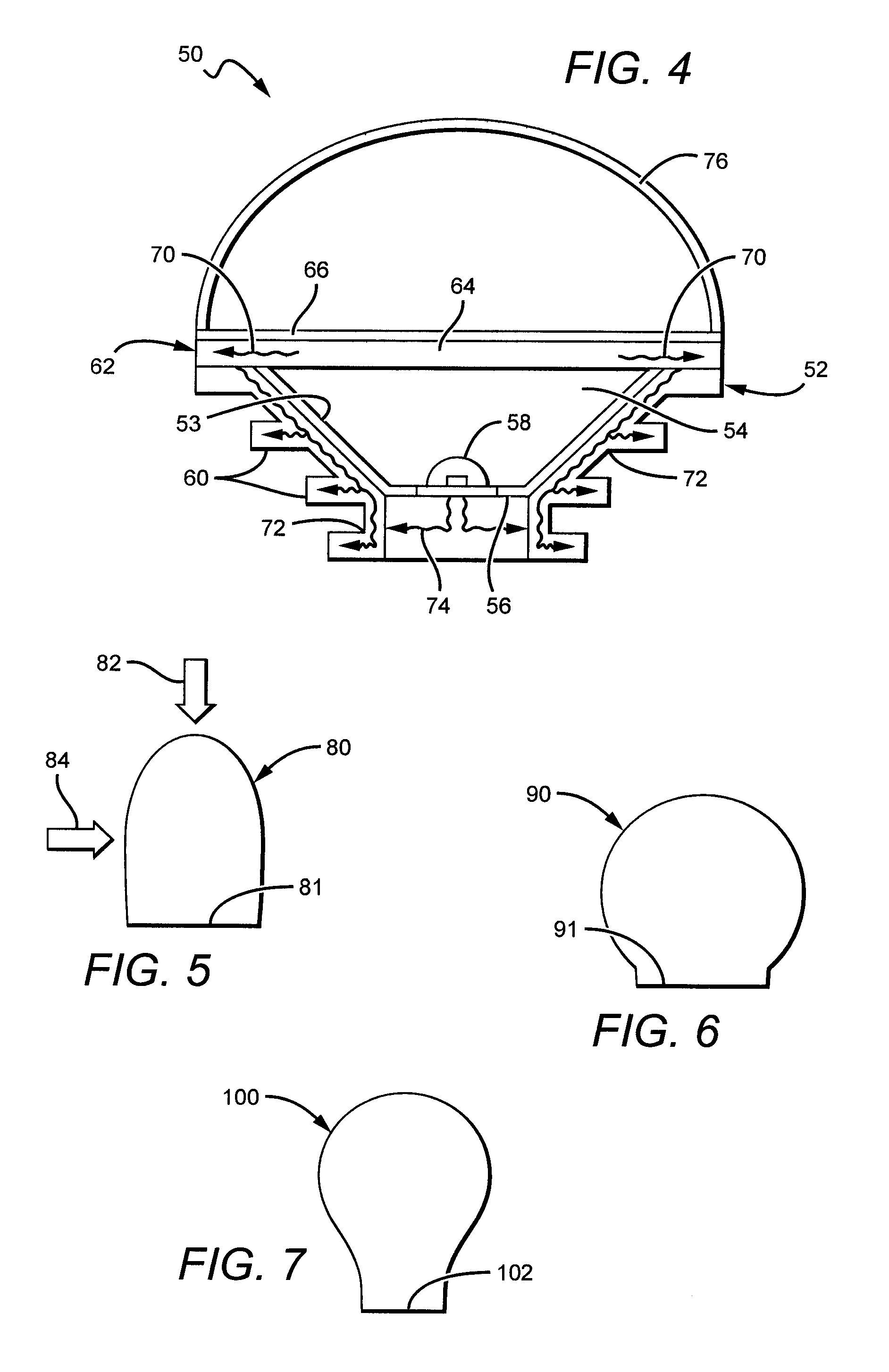
[0089]The present invention is directed to different embodiments of lamp or bulb structures that are efficient, reliable and cost effective, and that in some embodiments can provide an essentially omnidirectional emission pattern from directional emitting light sources, such as forward emitting light sources. The present invention is also directed to lamp structures using solid state emitters with remote conversion materials (or phosphors) and remote diffusing elements or diffuser. In some embodiments, the diffuser not only serves to mask the phosphor from the view by the lamp user, but can also disperse or redistribute the light from the remote phosphor and / or the lamp's light source into a desired emission pattern. In some embodiments the diffuser dome can be arranged to disperse forward directed emission pattern into a more omnidirectional pattern useful for general lighting applications. The diffuser can be used in embodiments having two-dimensional as well as three-dimensional ...


PUM

PropertyMeasurementUnit
Fractionaaaaaaaaaa
Fractionaaaaaaaaaa
Luminous fluxaaaaaaaaaa

Abstract

An LED lamp or bulb is disclosed that comprises a light source, a heat sink structure and an optical cavity. The optical cavity comprises a phosphor carrier having a conversions material and arranged over an opening to the cavity. The phosphor carrier comprises a thermally conductive transparent material and is thermally coupled to the heat sink structure. An LED based light source is mounted in the optical cavity remote to the phosphor carrier with light from the light source passing through the phosphor carrier. A diffuser dome is included that is mounted over the optical cavity, with light from the optical cavity passing through the diffuser dome. The diffuser dome can disperse the light passing through it into the desired emission pattern, such as omnidirection. In one embodiment, the light source can be blue emitting LED and the phosphor carrier can include a yellow phosphor, with the LED lamp or bulb emitting a white light combination of LED and phosphor light.

Description

[0001]This application claims the benefit of U.S. Provisional Patent Application Ser. No. 61 / 339,516, filed on Mar. 3, 2010, U.S. Provisional Patent Application Ser. No. 61 / 339,515, filed on Mar. 3, 2010, U.S. Provisional Patent Application Ser. No. 61 / 386,437, filed on Sep. 24, 2010, U.S. Provisional Patent Application Ser. No. 61 / 434,355, filed on Jan. 19, 2011, U.S. Provisional Patent Application Ser. No. 61 / 435,326, filed on Jan. 23, 2011, and U.S. Provisional Patent Application Ser. No. 61 / 435,759, filed on Jan. 24, 2011BACKGROUND OF THE INVENTION[0002]1. Field of the Invention[0003]This invention relates to solid state lamps and bulbs and in particular to efficient and reliable light emitting diode (LED) based lamps and bulbs capable of producing omnidirectional emission patterns.[0004]2. Description of the Related Art[0005]Incandescent or filament-based lamps or bulbs are commonly used as light sources for both residential and commercial facilities. However, such lamps are hi...

Claims


Application Information

Patent Timeline
IPC IPC(8): F21V9/16F21V11/00F21V9/00
CPCF21Y2101/02F21K9/56F21V3/02F21V29/773F21K9/135F21V29/505F21V29/767F21V3/0481F21K9/232F21K9/64F21Y2115/10F21V3/12
Inventor TONG, TAOLE TOQUIN, RONANKELLER, BERNDTARSA, ERICYOUMANS, MARKLOWES, THEODOREMEDENDORP, JR., NICHOLAS W.VAN DE VEN, ANTONYNEGLEY, GERALD
Owner IDEAL IND LIGHTING LLC
Why Eureka
Try Eureka