High-pressure injector

Active Publication Date: 2011-11-10
LIEBHERR COMPONENTS DEGGENDORF GMBH
View PDF36 Cites 12 Cited by
  • Summary
  • Abstract
  • Description
  • Claims
  • Application Information

AI Technical Summary

Benefits of technology

[0003]The present invention will therefore present a high-pressure injector

Problems solved by technology

The high-pressure injector therefore has a relatively compli

Method used


Image

  • High-pressure injector
  • High-pressure injector

Examples


Example

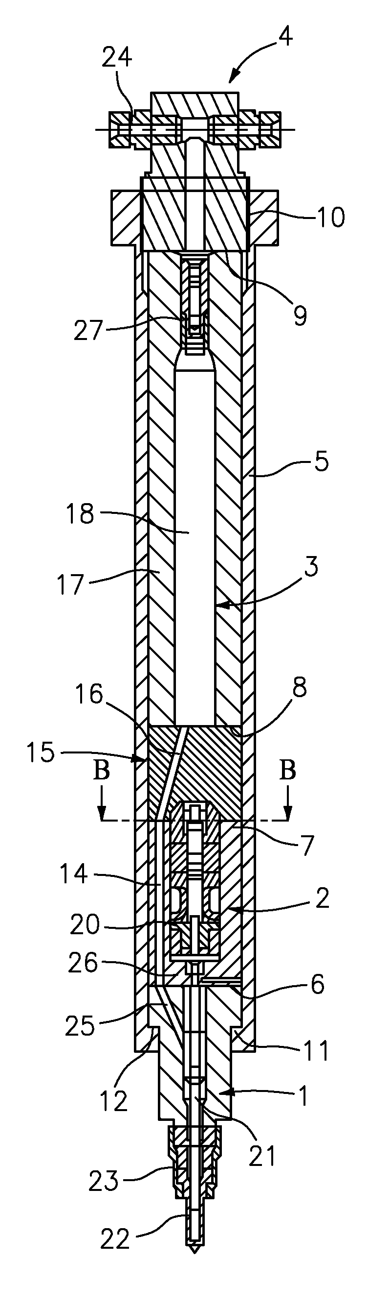
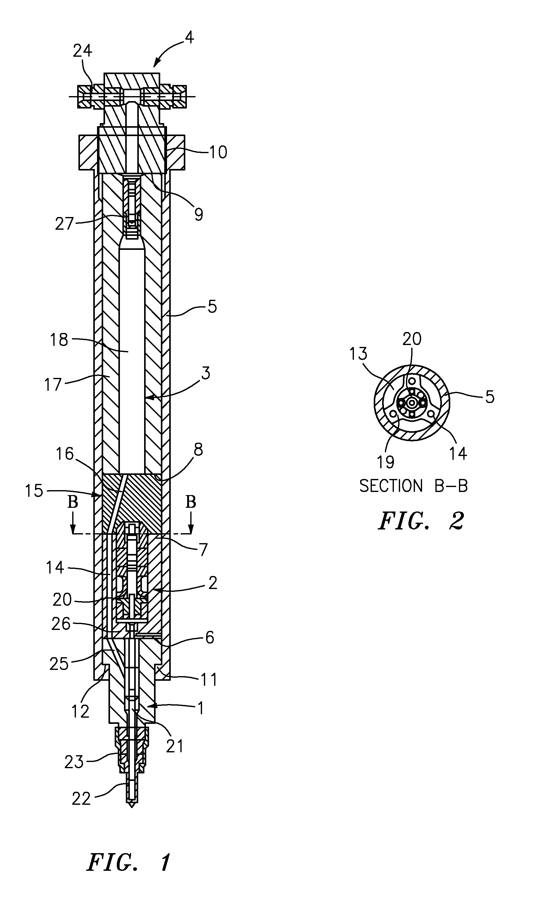
[0049]An embodiment of a high-pressure injector in accordance with the invention is shown in FIGS. 1 and 2. The high-pressure injector in this respect includes an injector unit 1, a drive unit 2 for driving the injector unit 1, a high-pressure storage unit 3 for supplying the injector unit 1 with fuel and a high-pressure connection 4. The high-pressure injector in accordance with the invention furthermore has a housing 5. The injector unit 1, the drive unit 2, the high-pressure storage unit 3 as well as the high-pressure connection 4 are in this respect arranged behind one another in the longitudinal direction of the high-pressure injector and abut one another or an intermediate piece 15 in contact zones (which each lie between two assemblies).

[0050]The mechanical connection of the individual assemblies now takes place in accordance with the invention via the housing 5 which completely envelops the drive unit 2 and the high-pressure unit 3. The assemblies are in this respect arrange...


PUM

PropertyMeasurementUnit
Pressureaaaaaaaaaa

Abstract

The present invention shows a high-pressure injector having the following assemblies: an injector unit (1), a drive unit (2) for driving the injector unit (1), preferably a high-pressure storage unit (3) for supplying the injector unit (1) with fuel, and a high-pressure connection (4). Provision is made in this respect that the high-pressure injector has a housing (5) in which a plurality of the named assemblies are arranged behind one another in the longitudinal direction of the injector, wherein the housing (5) completely envelops at least one of the named assemblies, in particular the drive unit (2) and/or the high-pressure storage unit (3). The high-pressure injector with the injector unit can be used in all types of internal combustion engines, preferably in diesel engines.

Description

BACKGROUND OF THE INVENTION[0001]The present invention relates to a high-pressure injector having an injector unit, having a drive unit for driving the injector unit and having a high-pressure connection. In an advantageous embodiment of the present invention, the high-pressure injector can furthermore have a high-pressure storage unit for supplying the injector unit with fuel.[0002]Such a high-pressure injector is known, for example, from document WO 2007 / 009279 A1. In this respect, each high-pressure injector includes a high-pressure storage unit (accumulator) to which the injector unit is connected at the front side via a cap nut. The drive unit for driving the injector unit is integrated into the high-pressure storage unit. The high-pressure injector therefore has a relatively complicated construction and is therefore expensive in manufacture.SUMMARY OF THE INVENTION[0003]The present invention will therefore present a high-pressure injector which has a simple construction and wh...

Claims


Application Information

Patent Timeline
IPC IPC(8): F02M61/14B23P17/00F02D1/00
CPCF02M47/027F02M55/002F02M55/005Y10T29/494F02M2200/16F02M2200/40F02M55/025F02M61/168
Inventor PIRKL, RICHARDBIGNION, EDGARKLEMP, WOLFRAM
Owner LIEBHERR COMPONENTS DEGGENDORF GMBH
Why Eureka
Try Eureka