Multiview video decoding apparatus, multiview video decoding method, multiview video decoding program, and multview video decoding integrated circuit

a multi-view video decoding and multi-view video technology, applied in the direction of color television with bandwidth reduction, signal generator with optical-mechanical scanning, signal generation, etc., can solve the problem of viewers of output images including errors to feel uncomfortable, and achieve the effect of accurate output images

Inactive Publication Date: 2011-11-24
PANASONIC CORP
View PDF3 Cites 18 Cited by
  • Summary
  • Abstract
  • Description
  • Claims
  • Application Information

AI Technical Summary

Benefits of technology

[0043]As shown in the diagram, in the case where an error is detected in a coded image L-2 to be decoded in the L-channel coded video stream among the multi-channel coded video streams, the decoded image L-2 including the error is not used, and a decoded image L-1 that is a previous output image of the same L channel is output as an output image for the left eye. Since a previous image and a current image are similar to each other in most cases, it is possible to perform error concealment that achieves a satisfactory image quality in this way.
[0079]In this way, the multiview video decoding apparatus according to the present invention makes it possible to reduce the possibility of causing a trouble in recognition of the content of the images of multi-channel coded video streams which are multiview coded to have a reference relationship between the multi-channels and reducing the influence of an error on the human visual recognition as much as possible, even when the error occurs in the decoding of the coded video streams.Further Information about Technical Background to This Application

Problems solved by technology

However, the aforementioned conventional multiview video decoding apparatus entails a problem that the apparatus may cause a viewer of output images including an error to feel uncomfortable in the case where an error occurs in the decoding of multi-channel video streams that are multiview coded to have a reference relationship.

Method used


Image

  • Multiview video decoding apparatus, multiview video decoding method, multiview video decoding program, and multview video decoding integrated circuit
  • Multiview video decoding apparatus, multiview video decoding method, multiview video decoding program, and multview video decoding integrated circuit
  • Multiview video decoding apparatus, multiview video decoding method, multiview video decoding program, and multview video decoding integrated circuit

Examples


embodiment 1

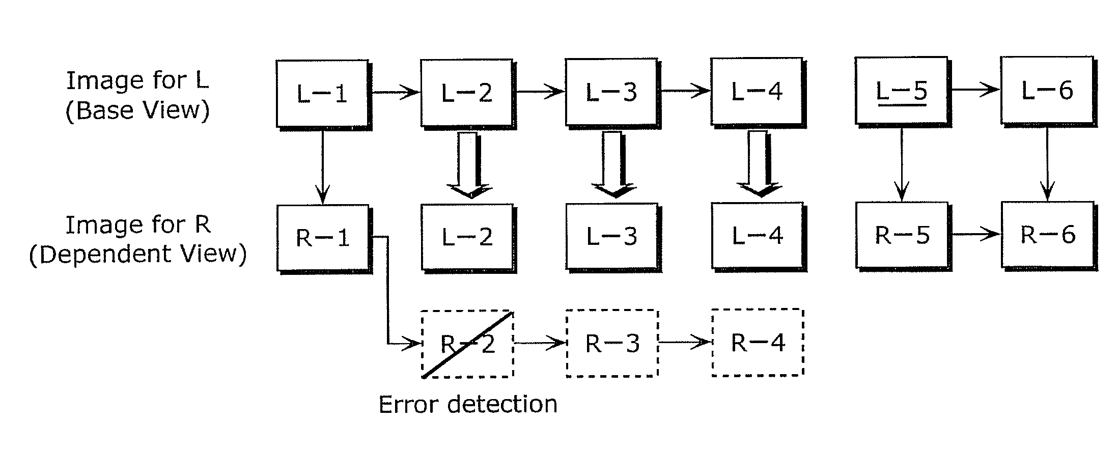
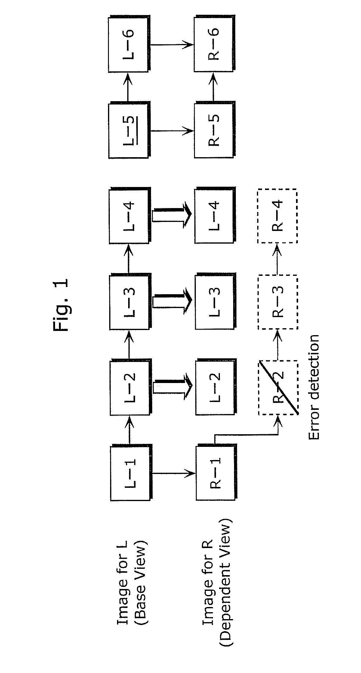
[0105]The following describes a multiview video decoding apparatus according to Embodiment 1 of the present invention.

[0106]Here, it is assumed in Embodiment 1 that the number of channels of the multiview coded video streams that are input to the multiview video decoding apparatus are multi-channel coded video streams of two channels that are an L-channel for the left eye and an R-channel for the right eye.

[0107]FIG. 3 is a block diagram of a structure of a multiview video decoding apparatus 100 according to Embodiment 1 of the present invention.

[0108]The multiview video decoding apparatus 100 is an apparatus which decodes a plurality of coded videos generated by coding videos from a plurality of viewpoints. More specifically, the multiview video decoding apparatus 100 is an apparatus which decodes a plurality of coded video streams multiview coded to have a mutual reference relationship. As shown in the diagram, the multiview video decoding apparatus 100 includes a decoding unit 11...

embodiment 2

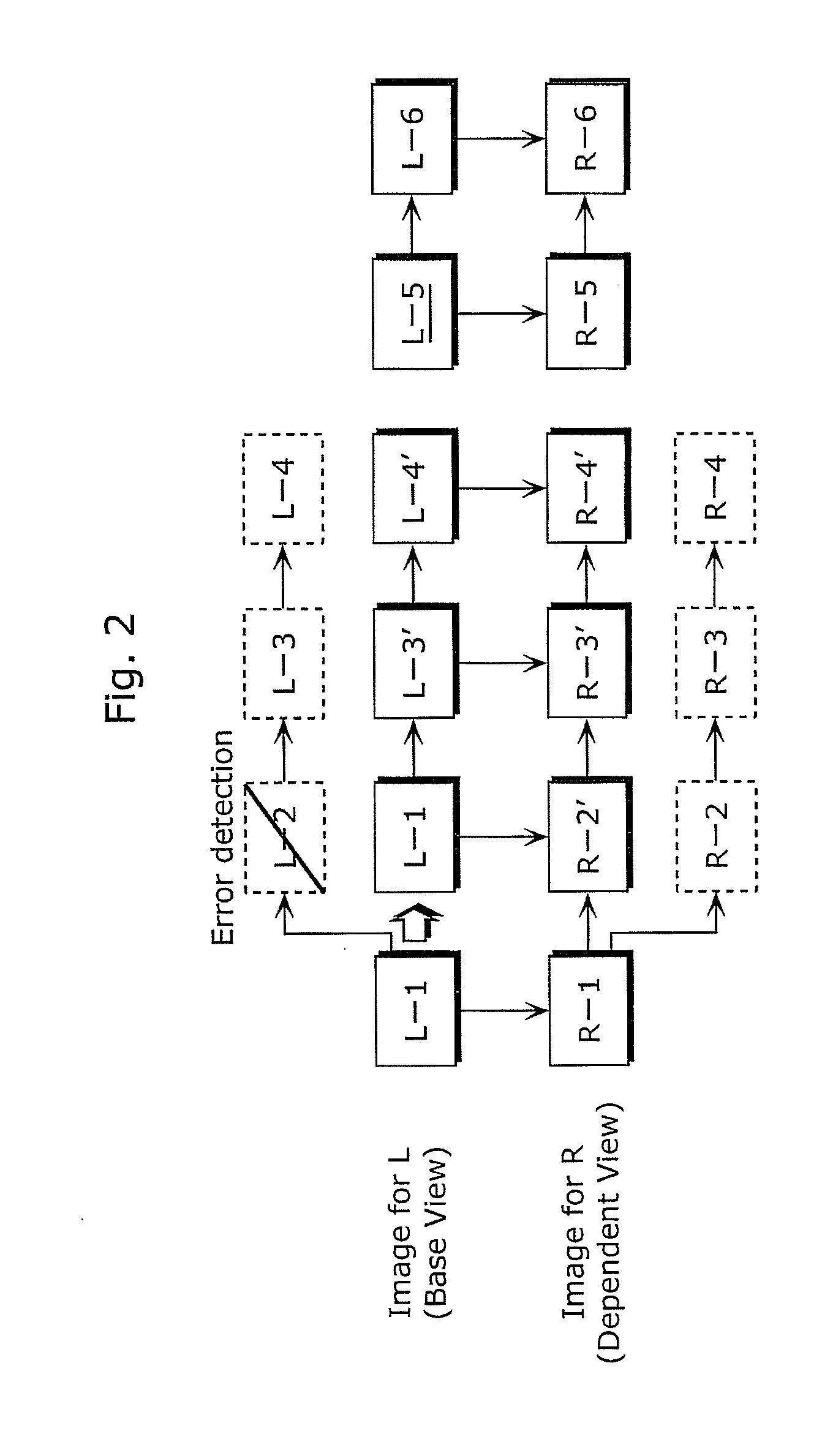
[0191]In Embodiment 1, it is assumed that the number of channels at the dependent view sides of the input coded video streams is one. However, in Embodiment 2, it is assumed that the number of channels at the dependent view sides of the input coded video streams is two.

[0192]FIG. 8 is a block diagram of a structure of a multiview video decoding apparatus 100 according to Embodiment 2 of the present invention.

[0193]As shown in the diagram, the multiview image decoding apparatus 100 according to Embodiment 2 includes a decoding unit 110, an error detecting unit 120, a decoded image replacing unit 130, and a buffer 140, similarly to the multiview image decoding apparatus 100 according to Embodiment 1. Here, three-channel coded video streams that are three coded videos are input to the multiview video decoding apparatus 100.

[0194]The buffer 140 is a memory in which decoded images are stored, and includes a decoded image buffer L141, a decoded image buffer R1142, and a decoded image buff...

embodiment 3

[0242]Embodiment 3 descries a multiview video decoding apparatus 200 including the multiview video decoding apparatus 100 according to any one of Embodiments 1 and 2.

[0243]FIG. 13 is a block diagram of a structure of the multiview video decoding apparatus 200 according to Embodiment 3 of the present invention. The diagram is based on FIG. 3 showing Embodiment 1 and shows the structure that is applicable to a DVD recorder (digital video recorder) and a Blu-ray disc recorder (or BD recorder), etc.

[0244]The multiview video decoding apparatus 200 includes a storage device 151, a storage device control unit 150, an integral control unit 160, a user interface 161, an audio decoding unit 170, a display unit 180, and a speaker 190, in addition to the multiview video decoding apparatus 100 as shown in FIG. 3.

[0245]The storage device control unit 150 reads out multiview coded video streams that are coded videos stored in the storage device 151 and sends coded video data to the decoding unit 1...


PUM


Abstract

A mutliview video decoding apparatus including: a decoding unit which decodes one of coded videos without reference to a coded video to generate one of decoded videos, and decodes an other one of coded videos with reference to the one of the coded videos to generate an other one of decoded videos; an error detecting unit which detests an error-source image in the decoded videos; and a decoded image replacing unit which replaces the error-source image with an image generated using a previous image that is decoded before the error-source image, without using the second decoded video that is other than the first decoded video that includes the error-source image, and replaces an associated error image that is associated with the error-source image with an image generated using an associated previous image that is associated with the error-source image, without using the first decoded video.

Description

CROSS REFERENCE TO RELATED APPLICATION[0001]This is a continuation application of PCT application No. PCT / JP2010 / 003424 filed on May 21, 2010, designating the United States of America.BACKGROUND OF THE INVENTION[0002](1) Field of the Invention[0003]The present invention relates to a multiview video decoding apparatus, a multiview video decoding method, a multiview video decoding program, and a multiview video decoding integrated circuit for decoding a plurality of multiview coded video streams having a reference relationship.[0004](2) Description of the Related Art[0005]There have been proposed three-dimensional image coding methods for enabling three-dimensional visual recognition by humans.[0006]Examples of such methods include a method of preparing two kinds of videos including at least one video for the left eye and one video for the right eye captured in mutually different directions, coding the videos such that the two kinds of videos have a mutual reference relationship, and ...

Claims


Application Information

Patent Timeline
Patent Type & Authority Applications(United States)
IPC IPC(8): H04N7/64H04N7/26H04N19/89H04N13/04H04N19/00H04N19/44H04N19/59H04N19/597H04N19/895
CPCH04N19/597H04N19/895H04N19/61H04N19/159
Inventor OKAJIMA, KAZUNORI
Owner PANASONIC CORP
Why Eureka
Try Eureka