
Wide angle imaging lens assembly

a wide-angle imaging and lens assembly technology, applied in the field of optical lens assembly, can solve the problems of reducing the system volume and length of the optical lens assembly with the wide-angle function, and the current optical lens assembly capable of performing a wide-angle function has a disadvantage of large volume and length, so as to achieve the effect of reducing system volume and length and favorable optical performan

Active Publication Date: 2018-11-01
SENYUN PRECISION OPTICAL CORP
View PDF5 Cites 8 Cited by
  • Summary
  • Abstract
  • Description
  • Claims
  • Application Information

AI Technical Summary

Benefits of technology

The invention provides a wide angle imaging lens that can be used in a smaller space while maintaining good optical performance. This lens has a unique design that allows for improved image quality with a smaller system size.

Problems solved by technology

The current optical lens assembly capable of performing a wide-angle function has a disadvantage of large volume and length.
As a result, reduction of the system volume and length of the optical lens assembly with the wide-angle function without sacrificing the favorable optical performance of said optical lens assembly has become one of the problems to be solved by research and development personnel in the pertinent field.

Method used


Image

  • Wide angle imaging lens assembly
  • Wide angle imaging lens assembly
  • Wide angle imaging lens assembly

Examples


Embodiment Construction

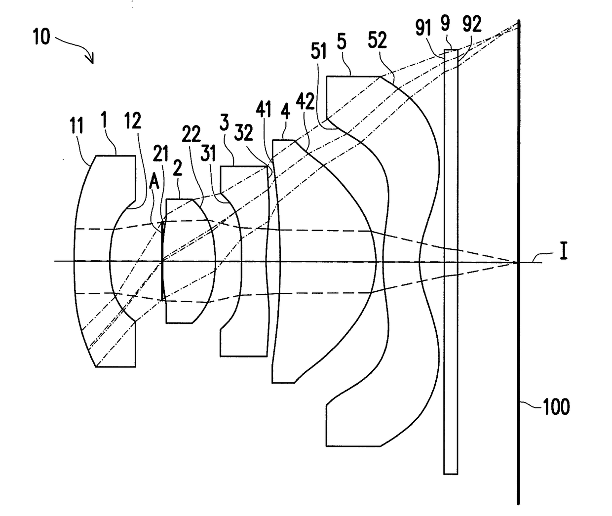
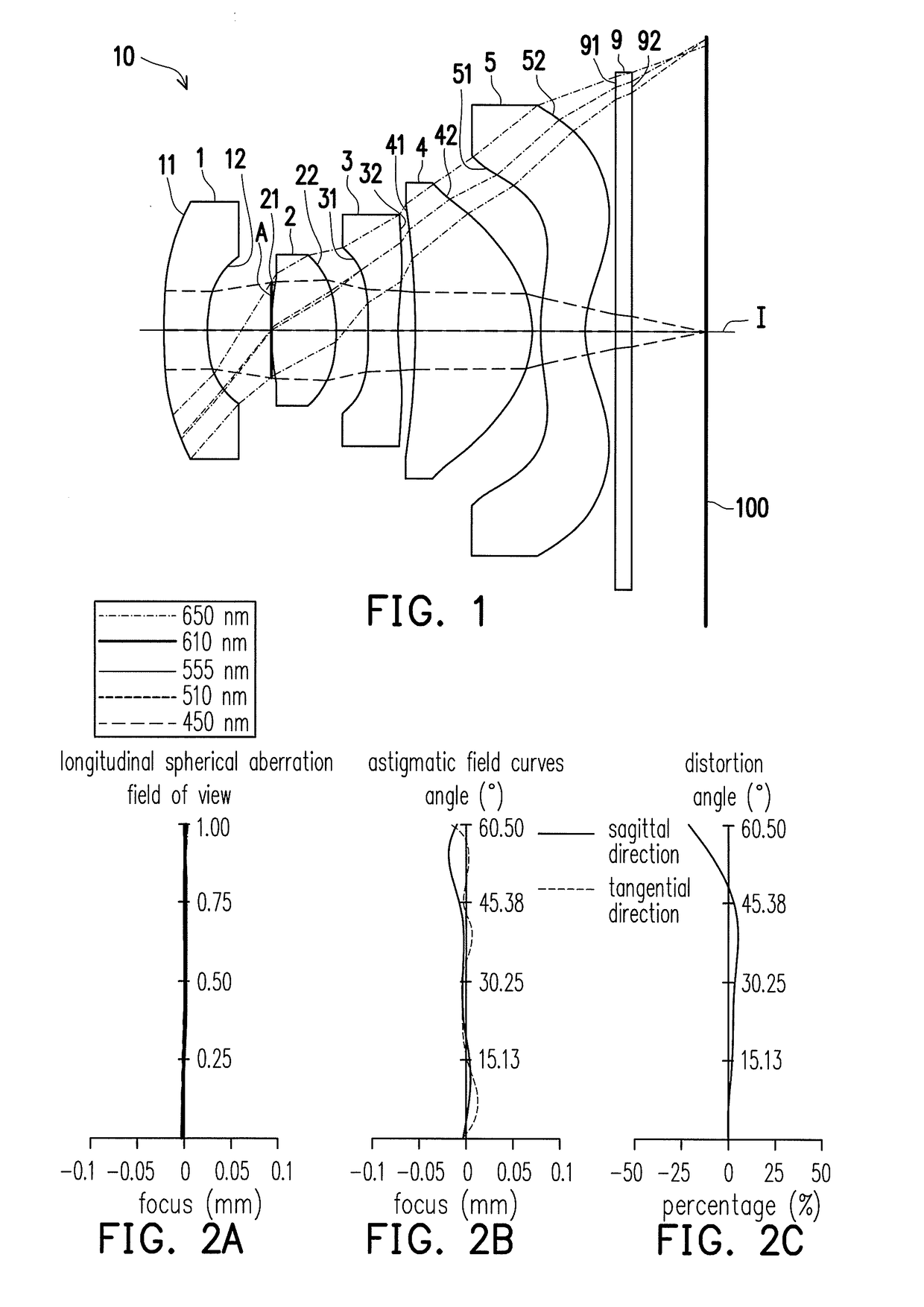
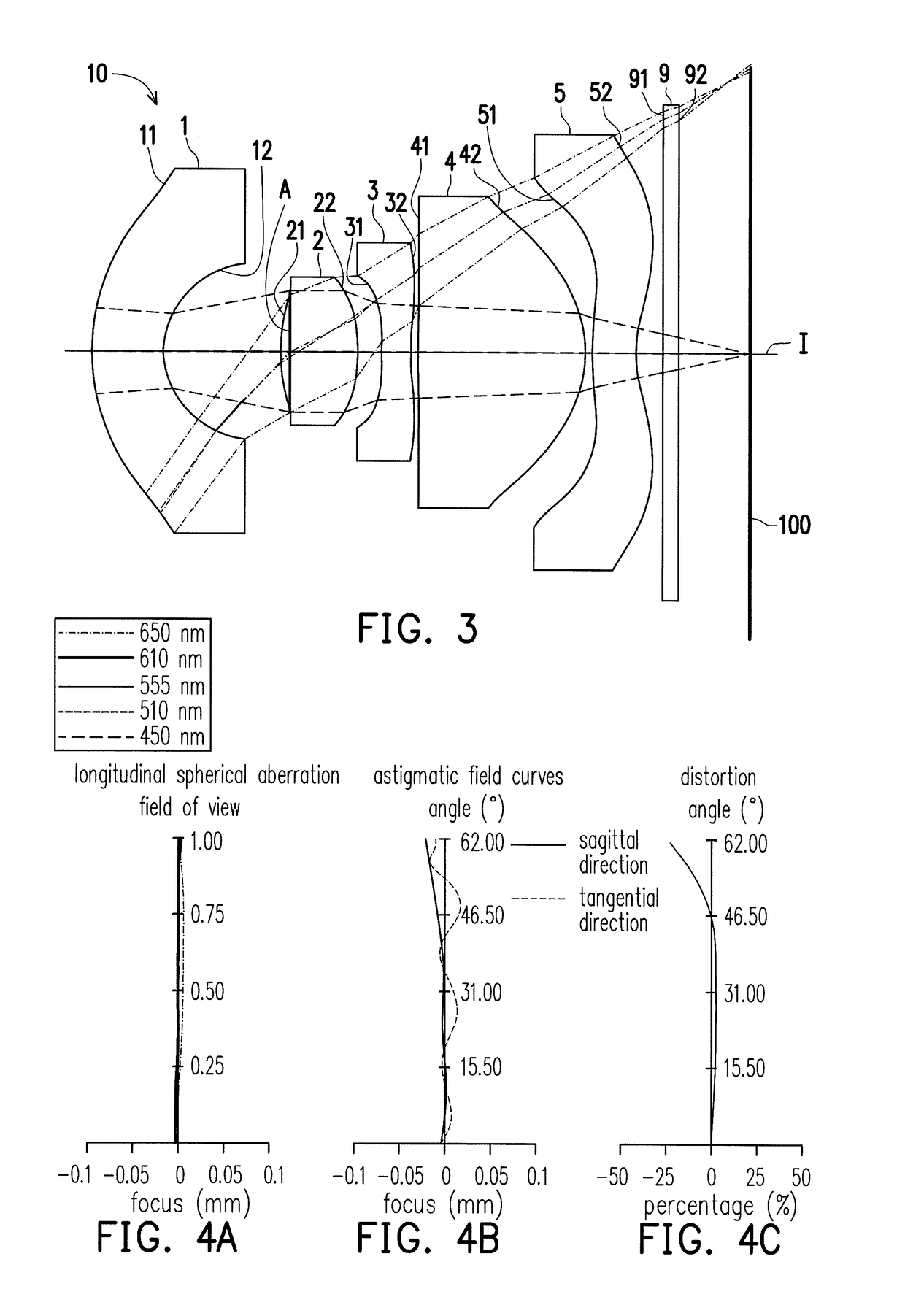
[0024]In the disclosure of this specification, “a lens element having a positive refractive power (or a negative refractive power)” means that a refractive power of the lens element on an optical axis, calculated by applying the theory of Gaussian optics, is positive (or is negative). In a wide angle imaging lens assembly, the lens elements are radially symmetrical with each other with the optical axis as an axis of symmetry. Each lens element has an object-side surface and an image-side surface opposite to the object-side surface. The object-side surface and the image-side surface are defined as a range which an imaging light passes through, wherein the imaging light includes a chief ray and a marginal ray. The object-side surface (or the image-side surface) has an area near the optical axis and a marginal area connected to and surrounding the area near the optical axis. The area near the optical axis is an area which the imaging light passes through on the optical axis. The margin...


PUM


Abstract

A wide angle imaging lens assembly includes a first lens element, an aperture, a second lens element, a third lens element, a fourth lens element, and a fifth lens element from an object side to an image side in order along an optical axis. The first lens element to the fifth lens element each includes an object-side surface facing the object side and an image-side surface facing the image side. The wide angle imaging lens assembly satisfies 1.25≤f / f2≤2.1 and (R5+R6) / (R5−R6)>0.25, where f is the effective focal length of the wide angle imaging lens assembly, f2 is the focal length of the second lens element, R5 is the radius of curvature of the object-side surface of the third lens element, and R6 is the radius of curvature of the image-side surface of the third lens element.

Description

CROSS-REFERENCE TO RELATED APPLICATION[0001]This application claims the priority benefit of Taiwan application serial no. 106114165, filed on Apr. 28, 2017. The entirety of the above-mentioned patent application is hereby incorporated by reference herein and made a part of this specification.BACKGROUND OF THE INVENTIONField of the Invention[0002]The invention relates to an optical lens assembly and particularly relates to a wide angle imaging lens assembly.Description of Related Art[0003]In recent years, the prevalence of mobile electronic devices boosts the vigorous development of technologies related to the image modules. An image module mainly includes an optical lens assembly, an optical sensor, and other elements. Along with the trend of slimness of the mobile electronic devices, the need for miniaturizing the optical lens assembly, the optical sensor, and other elements increases. However, to avoid the decrease in the quality of and effects on obtained images, the optical perf...

Claims


Application Information

Patent Timeline
IPC IPC(8): G02B13/00G02B9/60
CPCG02B13/0045G02B5/208G02B9/60G02B13/06G02B13/18
Inventor HSIEH, TIEN-LIANG
Owner SENYUN PRECISION OPTICAL CORP
Learn More