Image Data Analyzing Device, Image Data Analyzing Method, and Computer Program

a technology of image data and analyzing method, which is applied in the field of image data analyzing device, image data analyzing method, and computer program, can solve the problems of inability to output images in an appropriate size, inability to detect the roughness of pixels of digital cameras, and inability to always achieve the effect of reducing the difficulty of image outpu

Inactive Publication Date: 2009-03-05
SEIKO EPSON CORP
View PDF13 Cites 9 Cited by
  • Summary
  • Abstract
  • Description
  • Claims
  • Application Information

AI Technical Summary

Benefits of technology

[0024]If the computer is caused to read these programs and realize the respective functions described above, it is possible to output an image in an appropriate size.

Problems solved by technology

However, when it is attempted to output the images in an excessively large size, roughness of pixels of the digital camera becomes conspicuous because the images are enlarged.
As a result, a quality of output images may be deteriorated.
However, even if the proposed technique is adopted, images cannot always be outputted in an appropriate size.
In other words, even if images are photographed with the same number of pixels, the images cannot always withstand enlargement to the same size.

Method used


Image

  • Image Data Analyzing Device, Image Data Analyzing Method, and Computer Program
  • Image Data Analyzing Device, Image Data Analyzing Method, and Computer Program
  • Image Data Analyzing Device, Image Data Analyzing Method, and Computer Program

Examples


first modification

D-1. First Modification

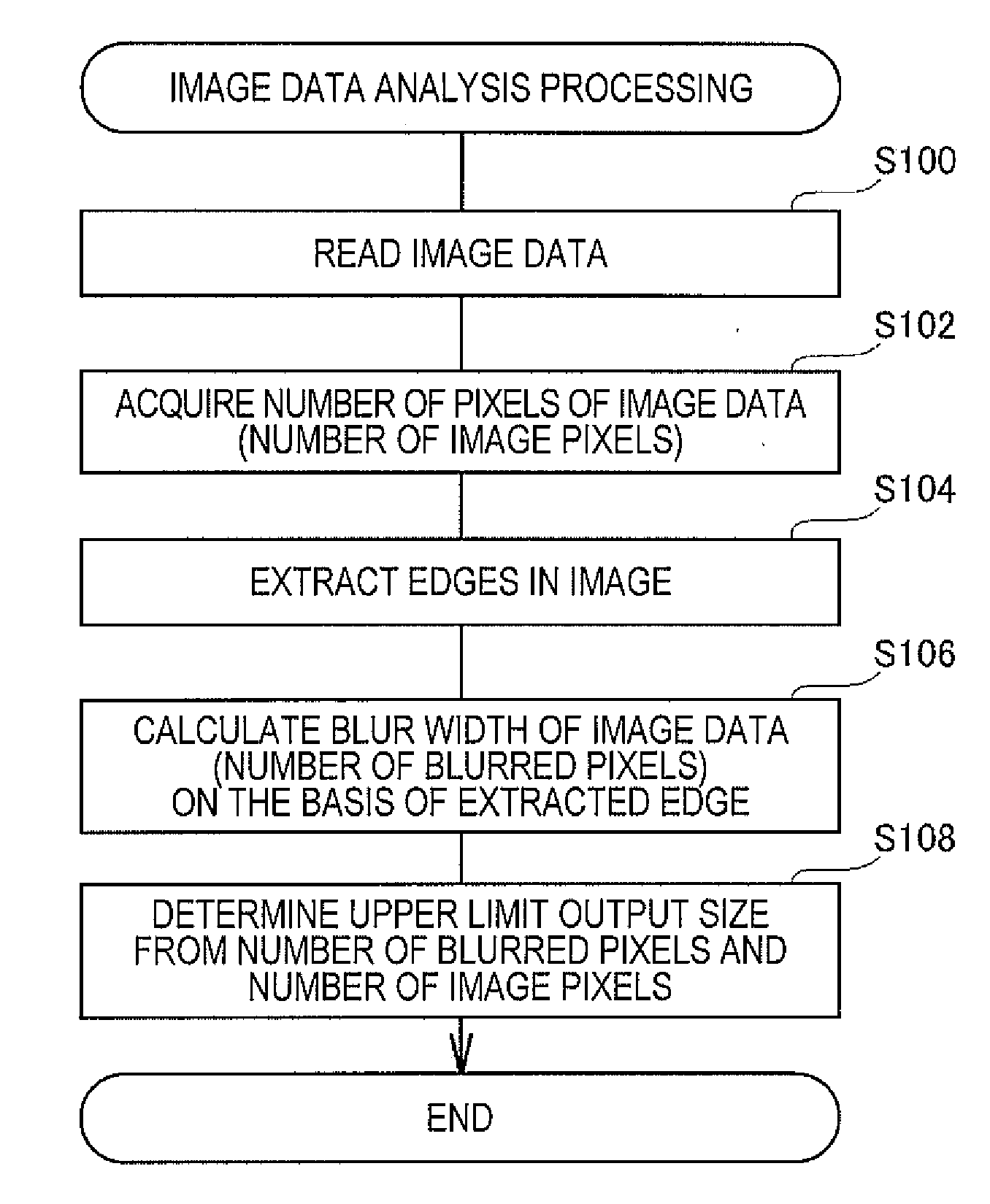
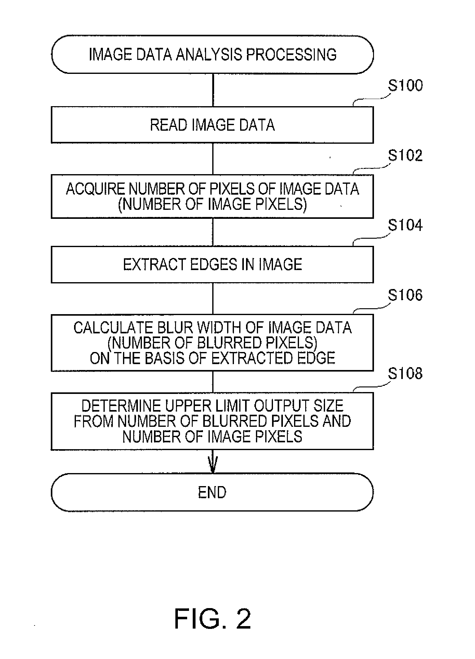
[0071]In the explanation of the embodiment described above, it is assumed that an upper limit output size in printing an entire image is determined (see step S108 in FIG. 2). However, an upper limit output size in printing a part of an image rather than an entire image may be determined.

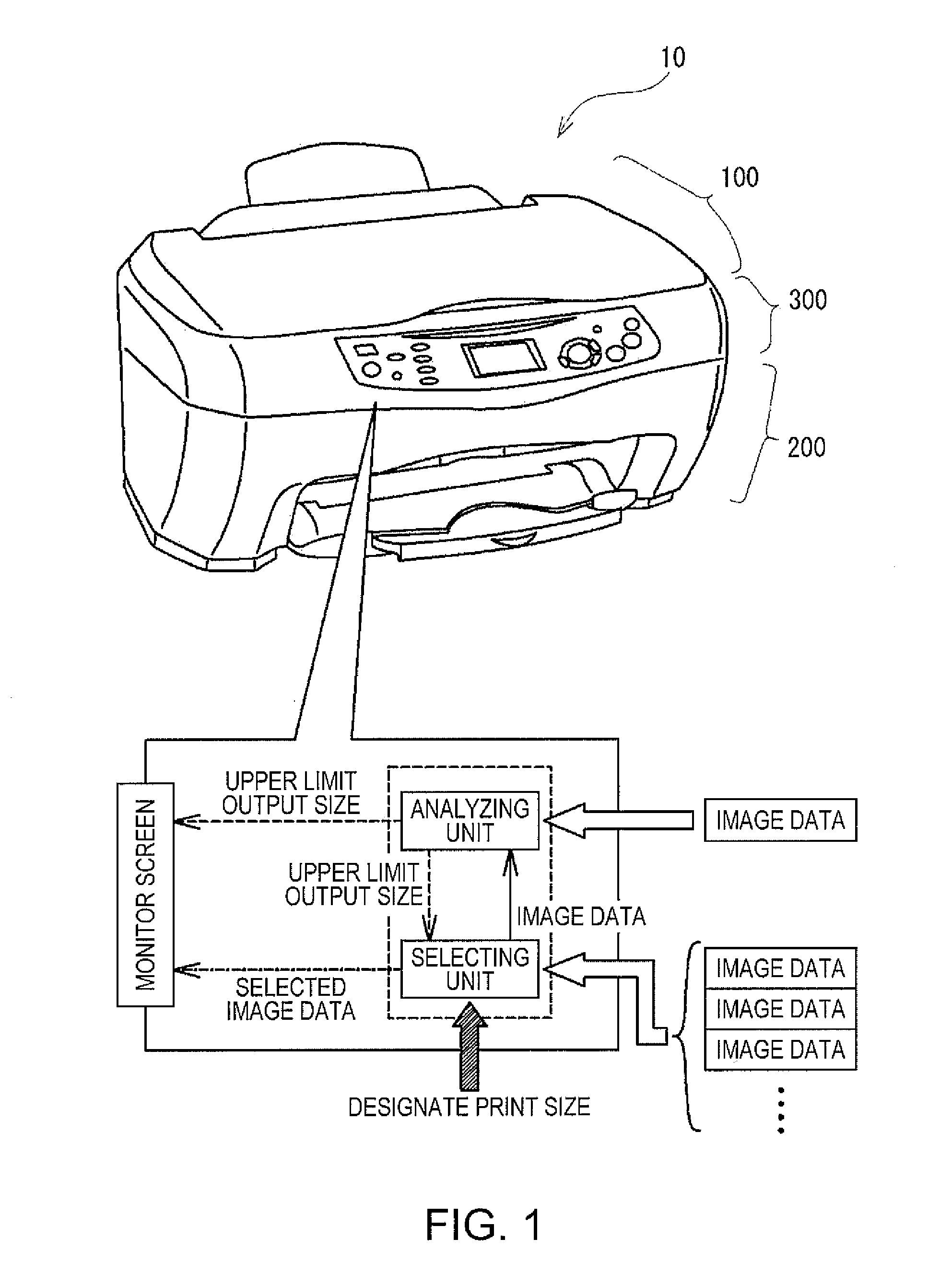
[0072]FIG. 11 is a diagram for explaining a state in which a user selects a part of an image. As shown in the figure, an image and a cursor are displayed on the monitor screen of the control unit 300. Therefore, the user can select, by operating the cursor while looking at the monitor screen, a portion desired to be printed. When the user selects the portion desired to be printed, the control unit 300 extracts data of the portion selected by the user and acquires the number of blurred pixels and the number of image pixels from the extracted data. To acquire the number of blurred pixels, the control unit 300 only has to apply the edge extraction processing to the extracted data ...

second modification

D-2. Second Modification

[0074]In the explanation of the embodiment described above, since a visibility limit slightly fluctuates depending on a size of a print sheet, it is assumed that a value of the visibility limit is changed for each of sizes of print sheets to determine an upper limit output size (see FIG. 7B). However, the upper limit output size may be determined by changing value of the visibility limit according to not only a size of a print sheet but also a distance for enjoying an image.

[0075]FIG. 12 is a diagram for conceptually explaining a state in which a visibility limit changes depending on a distance for enjoying an image. As shown in the figure, when the distance for enjoying an image increases, the visibility limit increases in proportion to the increase in the distance. For example, when a user sticks the image to a wall or the like and enjoys the image, the visibility limit is larger compared with that in enjoying the image at hand because the distance for enjo...


PUM


Abstract

An image data analyzing device that reads and analyzes image data includes a number-of-blurred-pixels detecting unit that detects a number of blurred pixels, which is a number of pixels indicating blur width of a contour in an image represented by the image data, a number-of-image-pixels acquiring unit that acquires a number of image pixels, which is a number of pixels related to a size of the image represented by the image data, and an upper-limit-output-size determining unit that determines, on a basis of the number of blurred pixels and the number of image pixels of the image data, an allowable upper limit output size of an image outputted by using the image data.

Description

BACKGROUND[0001]1. Technical Field[0002]The present invention relates to a technique for outputting, in an appropriate size, an image stored as digital data.[0003]2. Related Art[0004]In these days, images can be readily treated as digital data. For example, when a digital camera is used, photographs as high in quality as silver halide photographs can be easily taken. When photographed digital data is supplied to a printing apparatus such as an ink-jet printer, high-quality printed images can also be easily obtained.[0005]Since images are digital data, it is also easy to changes sizes of the images when the images are outputted. For example, when the images are printed by the printing apparatus, the images are enlarged or reduced according to a sheet size. Alternatively, when the images are displayed on a display device or the like, the images can be enlarged or reduced according to a size of a display area.[0006]However, when it is attempted to output the images in an excessively la...

Claims


Application Information

Patent Timeline
Patent Type & Authority Applications(United States)
IPC IPC(8): G06K9/03
CPCG06T7/0002H04N1/3935G06T2207/30168H04N1/00002H04N1/00005H04N1/00037H04N1/00039H04N1/00047H04N1/0005H04N1/00068H04N1/00076H04N1/0035H04N1/00453H04N1/00482H04N1/2307H04N1/2323H04N1/233H04N1/2338H04N1/2353H04N1/2392G06T2207/20192
Inventor NAKAJIMA, AYAHIROAISO, SEIJIMATSUZAKA, KENJITANAKA, TAKASHIGE
Owner SEIKO EPSON CORP
Why Eureka
Try Eureka