Three-dimensional autostereoscopic display and method for reducing crosstalk in three-dimensional displays and in other similar electro-optical devices

a three-dimensional display and display technology, applied in the field of three-dimensional (3d) autostereoscopic displays and other similar electrooptical devices, can solve the problems of autostereoscopic displays currently available on the market, and achieve the effects of reducing resolution, reducing resolution, and increasing the size of grating cells in the illuminating screen

Inactive Publication Date: 2010-11-23
MIHAJLOVIC ZORAN
View PDF3 Cites 10 Cited by
  • Summary
  • Abstract
  • Description
  • Claims
  • Application Information

AI Technical Summary

Benefits of technology

[0018]This invention is a three-dimensional display which can have several orders of magnitude more different views than a typical autostereoscopic display currently available on market. It can display much more than one view at a time (per each display unit) etc., with negligible crosstalk, negligible aberrations, and with satisfactory image quality. That autostereoscopic displays currently available on market can provide only so small number of views is a consequence primarily of the limitation of maximum number of frames per second, which the fastest displays currently commercially available, can support. In addition, two or more this three-dimensional displays can be easily combined in order to provide twice or more views than a design based on a single display unit, due to negligible crosstalk of this design. In addition, this design has also achieved various additional improvements of the image quality, such as that it can have as small pixel size and as small pixel pitch as needed, so pixel pitch can be in the range of the average human eye resolution, so depth resolution can be equal to the maximum visible by a human viewer.
[0019]Furthermore, this three-dimensional display does not suffer from a reduced image resolution, like some contemporary three-dimensional displays. One more advantage of this design is that the size of the whole group of sub-pixels which steer the light to all different directions can be of the smallest observable size in order the sub-pixel grouping not to be observable by an average human viewer, or it can be even smaller. This design has also achieved the improvement of the image quality as a result of the decrease of the size of the samples of Holographic (Diffractive) Optical Element, or as a result of the decrease of the size of pixels in any optical device in general. In addition, this three-dimensional display can also be flat, and is capable of displaying any kind of two-dimensional image by enforcing all views to be identical. This three-dimensional display can be either a monochromatic three-dimensional display or full color three-dimensional display.
[0020]This design of a three-dimensional display has also an advantage that an array of processors for three-dimensional image processing can be easily associated with said three-dimensional display. For example, each pixel of said three-dimensional display can be mapped one-to-one into a corresponding two-dimensional array of two-dimensional arrays processors, while each subpixel is mapped one-to-one into a corresponding two-dimensional arrays of processors, while said processors are connected as so-called systolic arrays of processors, where each processor in an array is connected to its neighboring processors and eventually to some other processors in the entire array. Said processors have to be able to perform desired three-dimensional image processing. As a consequence, three-dimensional image processing with this design of a three-dimensional display associated with said systolic arrays of processors becomes very fast and can be performed by trivial operations such as shifting values of pixels and / or subpixels to adjacent pixels and / or subpixels, etc. Of course, said processors have to be connected with data / address / control buses to said three-dimensional display, for example with optic fibers.
[0029]The advantage of this solution is that the size of grating cells in the illuminating screen IS can be made larger (For example by increasing the size of pixels, and the size of grating cells as a consequence, which would result in the decrease of resolution, but that can be tolerated for the illuminating screen to some extent. But the decrease of resolution can be tolerated much more for the illuminating screen, IS, than for the image display, S), in order to make possible to decrease the size of a Time-Variable Window TVW, since the increase of the size of grating cells results in the decrease of the angle between the main lobe and the first order side-lobes, so as a consequence the side-lobes intercept the Selecting Screen SS at a shorter distance from the center of the Time-Variable Window TVW. (As it was mentioned in Section 2, (Introduction), the area of each grating cell, which is a rectangular aperture, causes appearance of side-lobes in spite of sine grating being used for the grating cell, since the entire transfer function of the 3D display optimized here includes the transfer function of the rectangular aperture as one of its factors.)
[0030]In that case it is possible to decrease the size of the Time-Variable Window TVW as much as necessary to achieve that the angle between the main lobe and the first order side-lobes produced by the diffraction of the opening of the Time-Variable Window TVW is large enough to ensure that the side-lobes which the TVW itself produces do not reach the image display S, and instead go aside and intercept the non-transparent mask M (if first order side-lobes produced by the TVW go aside, then the side-lobes of the higher order than the first will also go aside and miss the image display). It is also possible to use here in this designs apodization, serrated aperture edges, proper dimensioning of the system, etc., in order to minimize the side-lobes produced by the diffraction of the opening of the Time-Variable Window TVW. But in this solution the minimization of the side-lobes produced by the diffraction of the opening of the Time-Variable Window TVW should be easier to achieve due to less constrained design solution, that is, due to removing the conflict of interests described at the beginning of this section.

Problems solved by technology

That autostereoscopic displays currently available on market can provide only so small number of views is a consequence primarily of the limitation of maximum number of frames per second, which the fastest displays currently commercially available, can support.

Method used


Image

  • Three-dimensional autostereoscopic display and method for reducing crosstalk in three-dimensional displays and in other similar electro-optical devices
  • Three-dimensional autostereoscopic display and method for reducing crosstalk in three-dimensional displays and in other similar electro-optical devices
  • Three-dimensional autostereoscopic display and method for reducing crosstalk in three-dimensional displays and in other similar electro-optical devices

Examples


Embodiment Construction

Brief Description of the Drawings

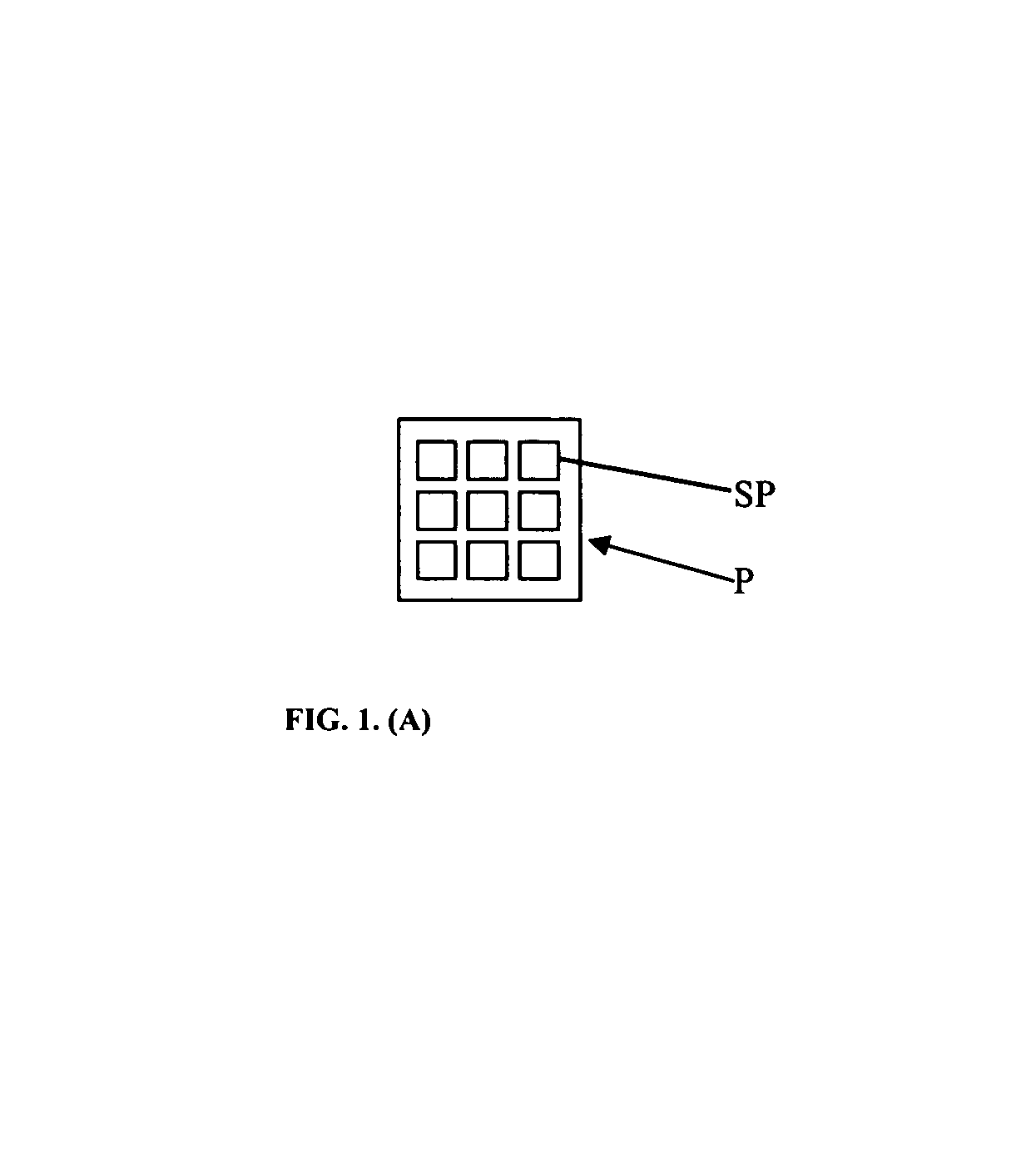
[0010]FIG. 1. (A): One pixel in display: P—Pixel ; SP—Subpixel (Front view).

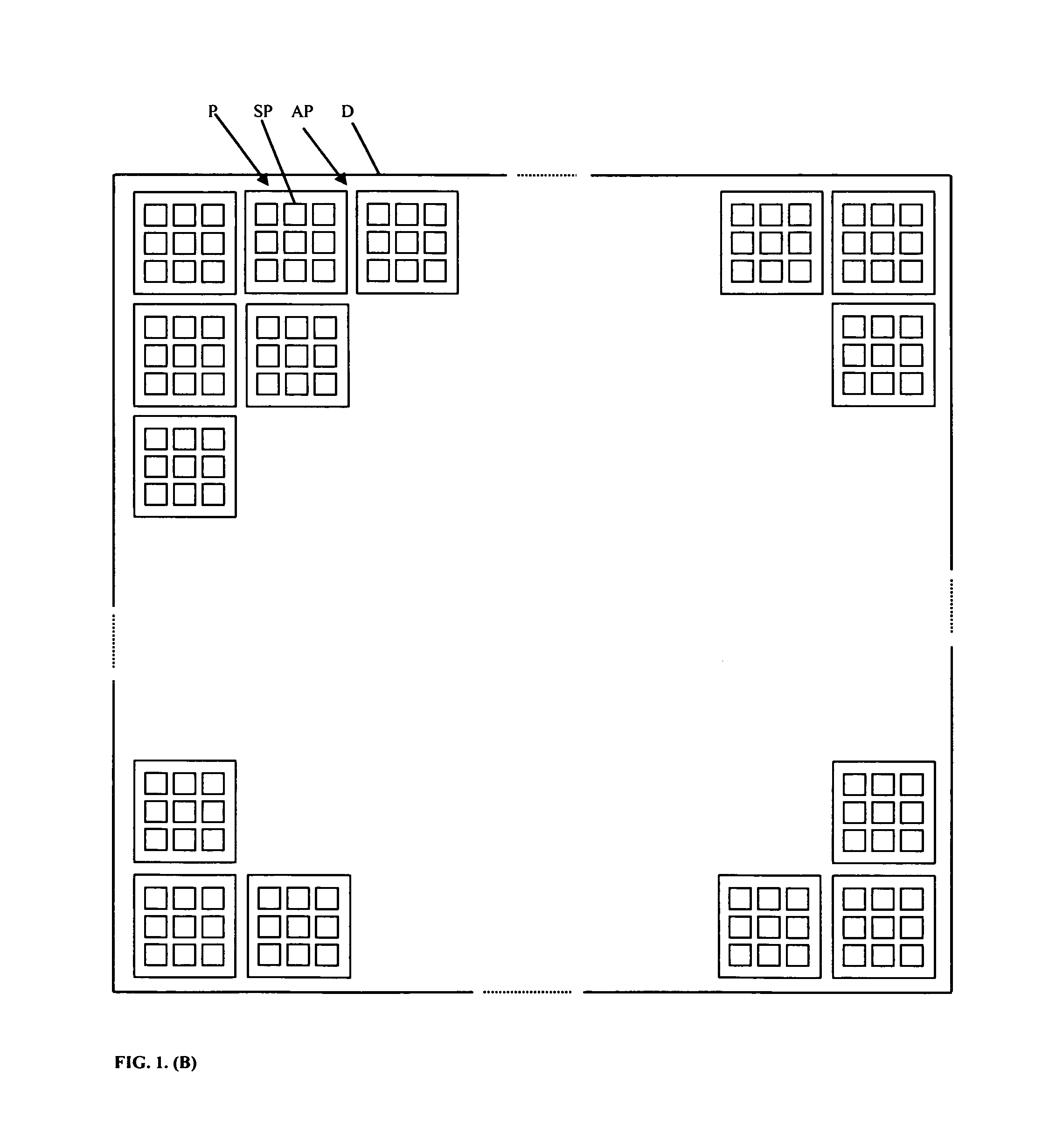
[0011]FIG. 1. (B): Display (shown partially). D—Display; P—Pixel ; SP—Subpixel ; AP—Entire array of pixels in said display (Front view).

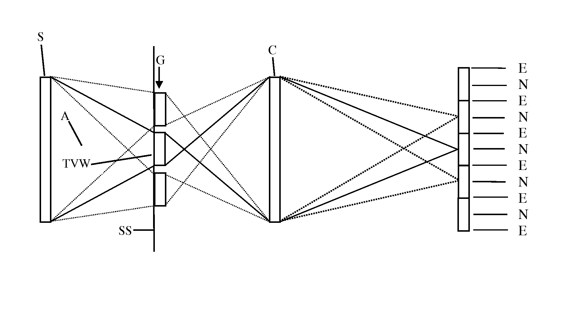
[0012]FIG. 2. IS—Illuminating Screen ; M—Non-transparent mask ; TVW—Time-variable window ; K—Direction of movement of the Time-variable window. (It is not necessary to activate the entire Illuminating screen for this particular position of the TVW—only down to the dotted line).

[0013]FIG. 3.: One pixel in display: P—Pixel ; H—Hole with micromirror (Front view).

[0014]FIG. 4.: Side view of one row of subpixels in FIG. 3. (cross-section): MM—Micromirror; AM—Active Mask ; PM —Passive mask; BP—Beam Preprocessor; CPA—Common Pixel Aperture; CPOC—Common Pixel Optical Component; II—Incident Illuminating light ray; AI—Light ray at the output of BP ; RIR—Reflected Illuminating light ray.

[0015]FIG. 5.: Beam Preprocessor (used in FIG. 4.): BP—Beam Preproce...


PUM

PropertyMeasurementUnit
sizeaaaaaaaaaa
sizeaaaaaaaaaa
sizeaaaaaaaaaa

Abstract

This Patent Application describes invention in form of a design of three-dimensional (3D) autostereoscopic displays and other similar electro-optical devices, and also describes a method for reducing crosstalk in said 3D displays and in other similar electro-optical devices, such as in the electro-optical devices that perform optical switching, optical processors, optical data storage, etc. The improvement of the image quality as a result of the decrease of the size of the samples of Holographic / Diffractive Optical Element without increased crosstalk and / or superposition of extraneous images in the image reconstruction is also achieved by the use of the invention described in this Patent Application.

Description

BACKGROUND OF THE INVENTION[0001]1. Field of Invention[0002]This invention relates to three-dimensional (3D) autostereoscopic displays and other similar electro-optical devices.[0003]2. Introduction[0004]Several 3D displays, such as 3D displays described in 1, 2, 4, 7, 5, 6, and some other similar 3D displays, all suffer from similar problems, such as crosstalk, aberrations, deformed Modulation Transfer Function, etc. As it is obvious from the examples listed here, many 3D displays suffer from crosstalk.[0005]It is possible to try to minimize that crosstalk, or any other distortion in the image, in several ways. The 3D display described in 1 and in 4 is based on the concept of grating cells (FIGS. 1(A), 1(B)). Each pixel of the display is divided into an array of subpixels, and each subpixel is covered with a diffraction grating cell of such period and orientation that it directs light to the center of corresponding (virtual) viewing slit when activated.[0006]The problem with the ar...

Claims


Application Information

Patent Timeline
Patent Type & Authority Patents(United States)
IPC IPC(8): G02B5/32G03H1/26G02B30/33
CPCG02B27/2214G02B27/42G02B27/4238G02B5/32G02B30/33G02B30/27
Inventor MIHAJLOVIC, ZORAN
Owner MIHAJLOVIC ZORAN
Why Eureka
Try Eureka