[0018] This invention is a three-dimensional display which can have several orders of magnitude more different views than a typical autostereoscopic display currently available on market. It can display much more than one view at a time (per each display unit) etc., with negligible crosstalk, negligible aberrations, and with satisfactory
image quality. That autostereoscopic displays currently available on market can provide only so small number of views is a consequence primarily of the limitation of maximum number of frames per second, which the fastest displays currently commercially available, can support. In addition, two or more this three-dimensional displays can be easily combined in order to provide twice or more views than a design based on a single display unit, due to negligible crosstalk of this design. In addition, this design has also achieved various additional improvements of the
image quality, such as that it can have as small pixel size and as small pixel
pitch as needed, so pixel
pitch can be in the range of the average
human eye resolution, so depth resolution can be equal to the maximum visible by a human viewer.
[0019] Furthermore, this three-dimensional display does not suffer from a reduced
image resolution, like some contemporary three-dimensional displays. One more
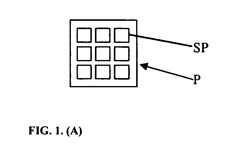
advantage of this design is that the size of the whole group of sub-pixels which steer the light to all different directions can be of the smallest
observable size in order the sub-pixel grouping not to be
observable by an average human viewer, or it can be even smaller. This design has also achieved the improvement of the image quality as a result of the decrease of the size of the samples of Holographic (Diffractive) Optical Element, or as a result of the decrease of the size of pixels in any optical device in general. In addition, this three-dimensional display can also be flat, and is capable of displaying any kind of two-dimensional image by enforcing all views to be identical. This three-dimensional display can be either a monochromatic three-dimensional display or
full color three-dimensional display.
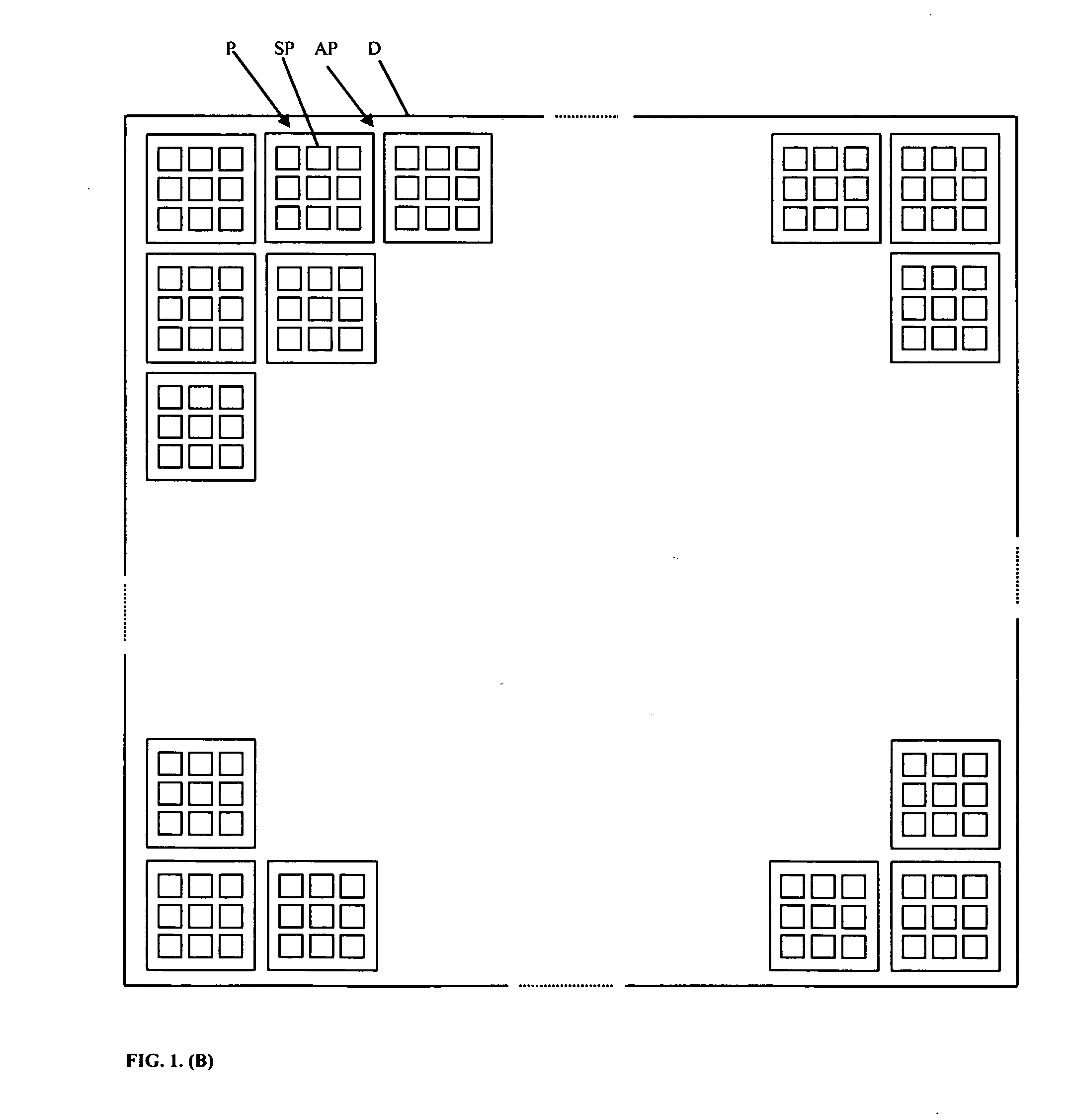
[0020] This design of a three-dimensional display has also an
advantage that an array of processors for three-dimensional
image processing can be easily associated with said three-dimensional display. For example, each pixel of said three-dimensional display can be mapped one-to-one into a corresponding two-dimensional array of two-dimensional arrays processors, while each subpixel is mapped one-to-one into a corresponding two-dimensional array of processors, while said processors are connected as so-called systolic arrays of processors, where each processor in an array is connected to its neighboring processors and eventually to some other processors in the entire array. Said processors have to be able to perform desired three-dimensional
image processing. As consequence, three-dimensional
image processing with this design of a three-dimensional display associated with said systolic arrays of processors becomes very fast and can be performed by trivial operations such as shifting values of pixels and / or subpixels to adjacent pixels and / or subpixels, etc. Of course, said processors have to be connected with data / address / control buses to said three-dimensional display, for example with optic fibers.
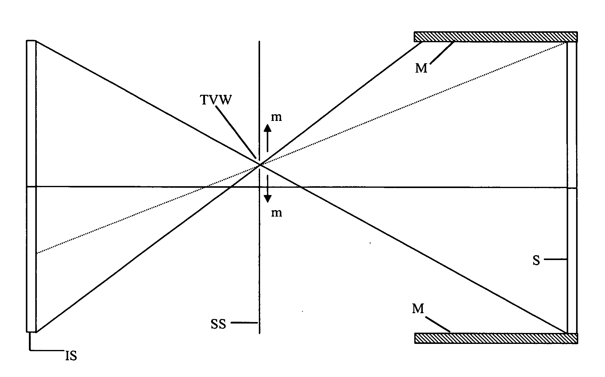
[0029] The
advantage of this solution is that the size of
grating cells in the illuminating screen IS can be made larger (For example by increasing the size of pixels, and the size of grating cells as a consequence, which would result in the decrease of resolution, but that can be tolerated for the illuminating screen to some extent. But the decrease of resolution can be tolerated much more for the illuminating screen, IS, than for the
image display, S), in order to make possible to decrease the size of a Time-
Variable Window TVW, since the increase of the size of grating cells results in the decrease of the angle between the
main lobe and the first order side-lobes, so as a consequence the side-lobes intercept the Selecting Screen SS at a shorter distance from the center of the Time-
Variable Window TVW. (As it was mentioned in Section 1.1, the area of each grating
cell, which is a
rectangular aperture, causes appearance of side-lobes in
spite of sine grating being used for the grating
cell, since the entire
transfer function of the 3D display optimized here includes the
transfer function of the
rectangular aperture as one of its factors.)
[0030] In that case it is possible to decrease the size of the Time-
Variable Window TVW as much as necessary to achieve that the angle between the
main lobe and the first order side-lobes produced by the
diffraction of the opening of the Time-Variable Window TVW is large enough to ensure that the side-lobes which the TVW itself produces do not reach the
image display S, and instead go aside and intercept the non-transparent
mask M (if first order side-lobes produced by the TVW go aside, then the side-lobes of the higher order than the first will also go aside and miss the
image display). It is also possible to use here in this designs
apodization, serrated aperture edges, proper
dimensioning of the
system, etc., in order to minimize the side-lobes produced by the
diffraction of the opening of the Time-Variable Window TVW. But in this solution the minimization of the side-lobes produced by the diffraction of the opening of the Time-Variable Window TVW should be easier to achieve due to less constrained design solution, that is, due to removing the conflict of interests described at the beginning of this section.

