Apparatus and method for producing plasma during milling for processing of material compositions

a technology of material composition and apparatus, applied in the field of apparatus and method for producing plasma during milling for processing of material composition, can solve the problems of time-consuming and energy-intensive conventional milling process

Inactive Publication Date: 2011-12-08
GENERAL ELECTRIC CO
View PDF6 Cites 19 Cited by
  • Summary
  • Abstract
  • Description
  • Claims
  • Application Information

AI Technical Summary

Benefits of technology

The invention provides two methods for creating a steady glow discharge plasma without causing damage or contamination: One involves placing a small amount of liquid into an electric field and allowing it to evaporate naturally through heat transfer; the other involves adding a few drops of liquid containing solvents to a larger volume of gas and then exposing them both to high-frequency electrical currents. These techniques allow researchers to safely examine samples without risking any harm during analysis.

Problems solved by technology

The technical problem addressed by this patent is finding new ways to improve mechanical alloying, which involves making changes to the chemical makeup of a material through mechanic means like grinding or mixing. Current methods are often slow and require high levels of energy, resulting in low efficiency. Additionally, sometimes there aren't enough interactions between the material and the surrounding gases during traditional milling processes, leading to incomplete formation of the desired product. Therefore, there is a need to find better techniques that overcome these issues.

Method used


Image

  • Apparatus and method for producing plasma during milling for processing of material compositions
  • Apparatus and method for producing plasma during milling for processing of material compositions
  • Apparatus and method for producing plasma during milling for processing of material compositions

Examples


Embodiment Construction

[0011]Example embodiments presented herein are described below in detail with reference to the accompanying drawings, where the same reference numerals denote the same parts throughout the drawings. Some of these embodiments may address the above and other needs.

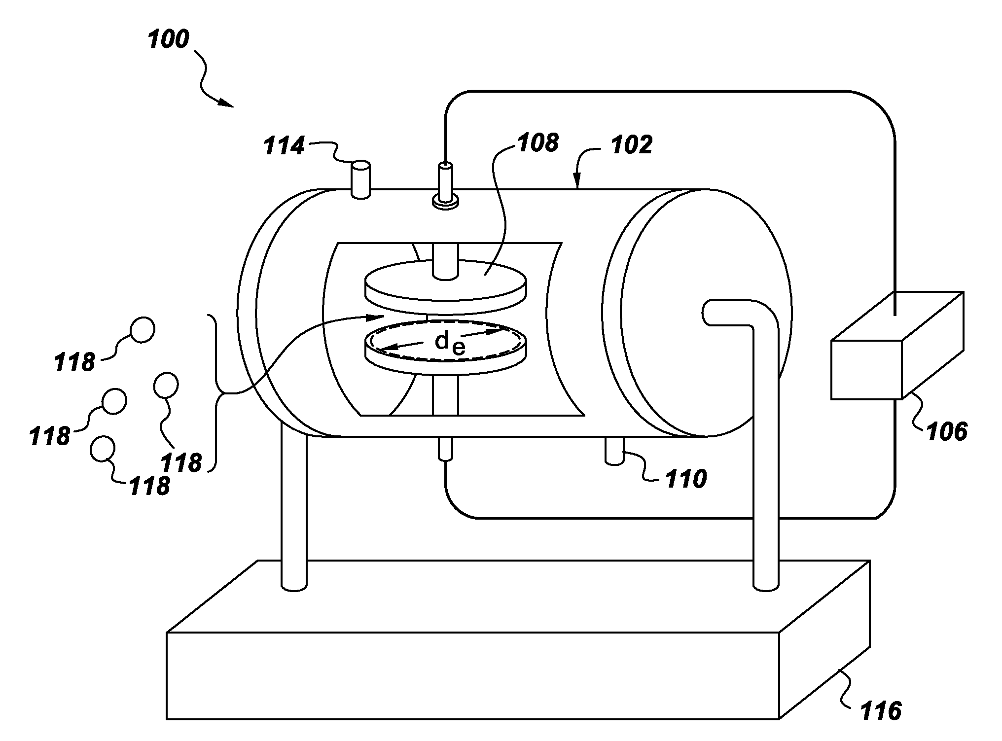
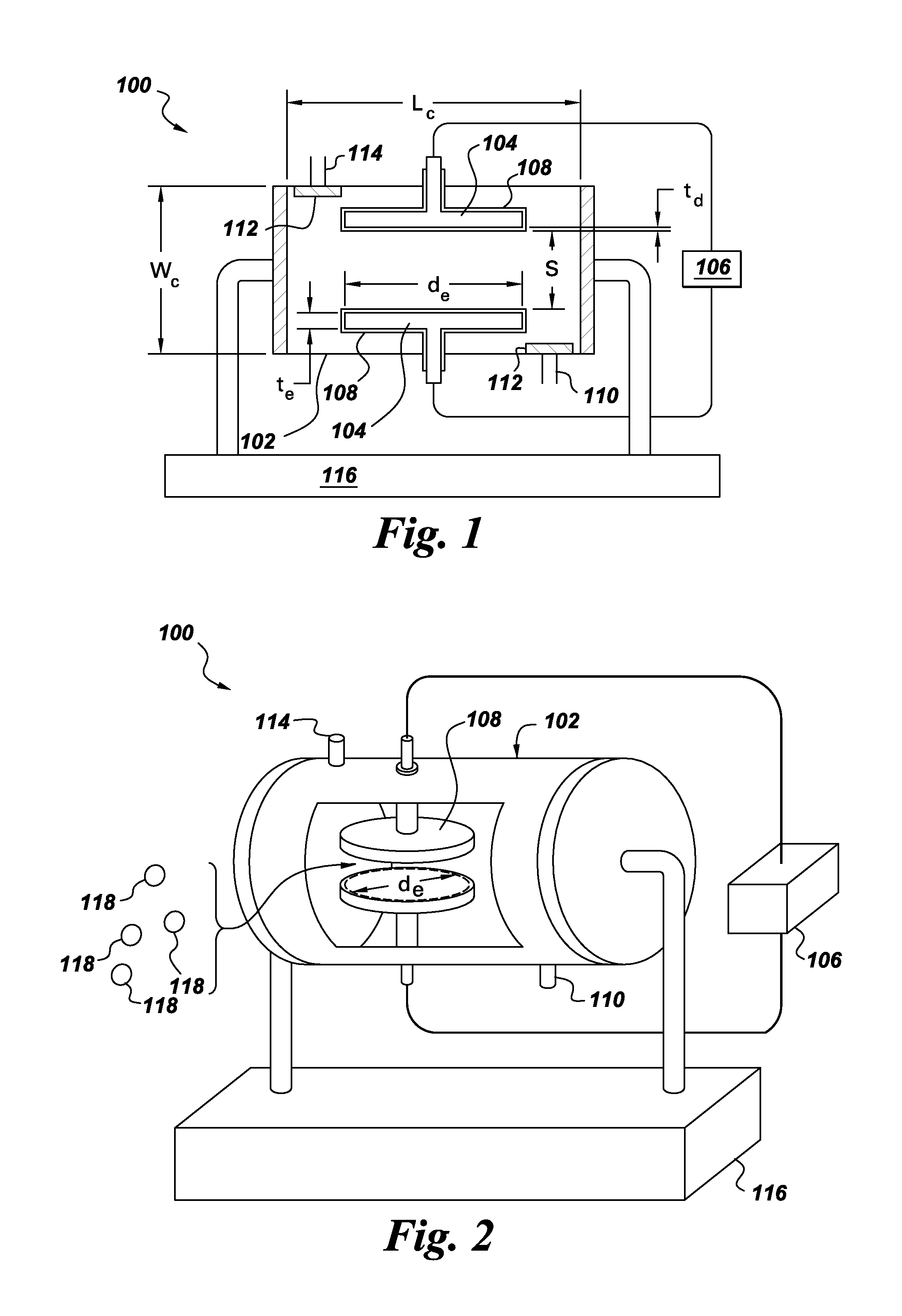
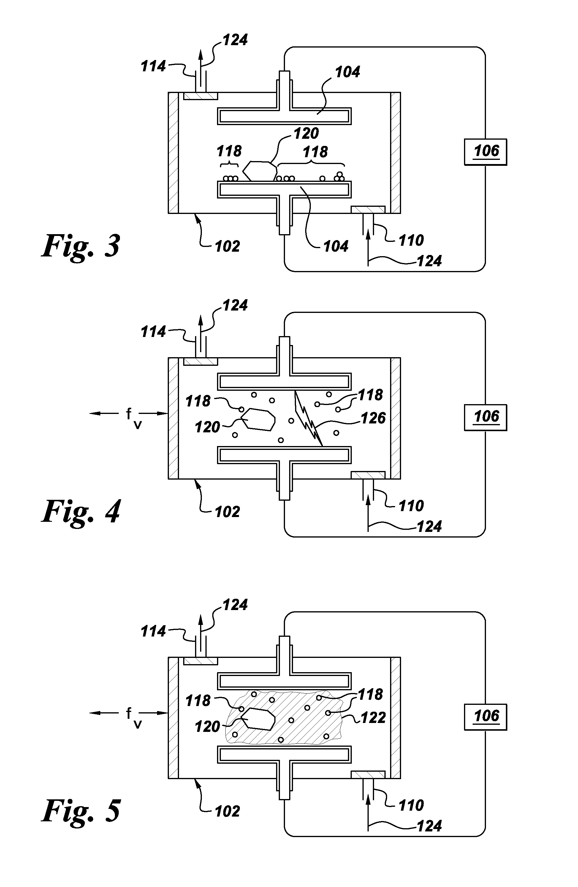
[0012]Referring to FIGS. 1 and 2, therein is shown an apparatus, such as a plasma generation system 100, configured in accordance with an example embodiment. The plasma generation system 100 includes a chamber 102. Generally, the chamber 102 may be formed of any material having a melting point more than about 150° C. and having a relatively low sputter yield under bombardment of the gaseous ions of the plasma generated by the plasma generation system 100 (the composition of the plasma is discussed further below). The chamber 102 may be formed, for example, substantially of PTFE (e.g., manufactured by E. I. du Pont de Nemours and Company (Wilmington, Del.) under the tradename TEFLON), a high-strength ceramic (for example, aga...


PUM

PropertyMeasurementUnit
Timeaaaaaaaaaa
Diameteraaaaaaaaaa
Diameteraaaaaaaaaa

Abstract

An apparatus, such as a plasma generation system, is provided. The apparatus can include a chamber that may be formed, for example, substantially of insulating material. The chamber can be configured to establish therein a stable glow discharge plasma having a pressure of at least about atmospheric pressure while vibrating a sample so as to be milled by bodies contained by the chamber. For example, the chamber may vibrate and/or rotate, and the chamber can include at least one body that includes insulating material and is free within the chamber. Associated methods are also provided.

Description


Claims


Application Information

Patent Timeline
Owner GENERAL ELECTRIC CO
Why Eureka
Try Eureka