
Staple gun

a technology of stapling and stapling blades, which is applied in the field of stapling guns, can solve the problems of user discomfort and vibration, and achieve the effect of easy downward rotation

Inactive Publication Date: 2011-12-08
HUANG CHIEN CHUAN
View PDF13 Cites 20 Cited by
  • Summary
  • Abstract
  • Description
  • Claims
  • Application Information

AI Technical Summary

Benefits of technology

[0005]The primary object of the present invention is to provide a staple gun wherein the effort arm from the fixed axle to the front end of' the arm is shortened such that the arm is easily pivoted downward when compared with the conventional staple gun. The resilient plate is bent to generate a significant force to eject the staples.

Problems solved by technology

However, although the user saves effort to operate the arm 76 when the distances of the effort arms “A” and “C” are way longer than the distances of the effort arms “B” and “D”, the resilient plate 74 generates significant vibration and the vibration often makes the user uncomfortable and has to hold the staple gun 7 firmly.

Method used


Image

  • Staple gun
  • Staple gun
  • Staple gun

Examples


Embodiment Construction

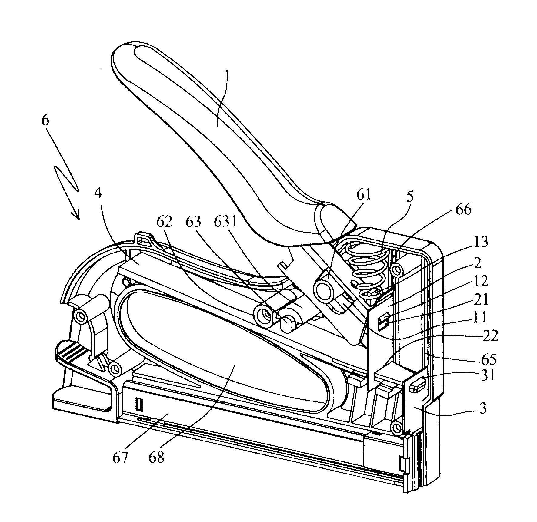
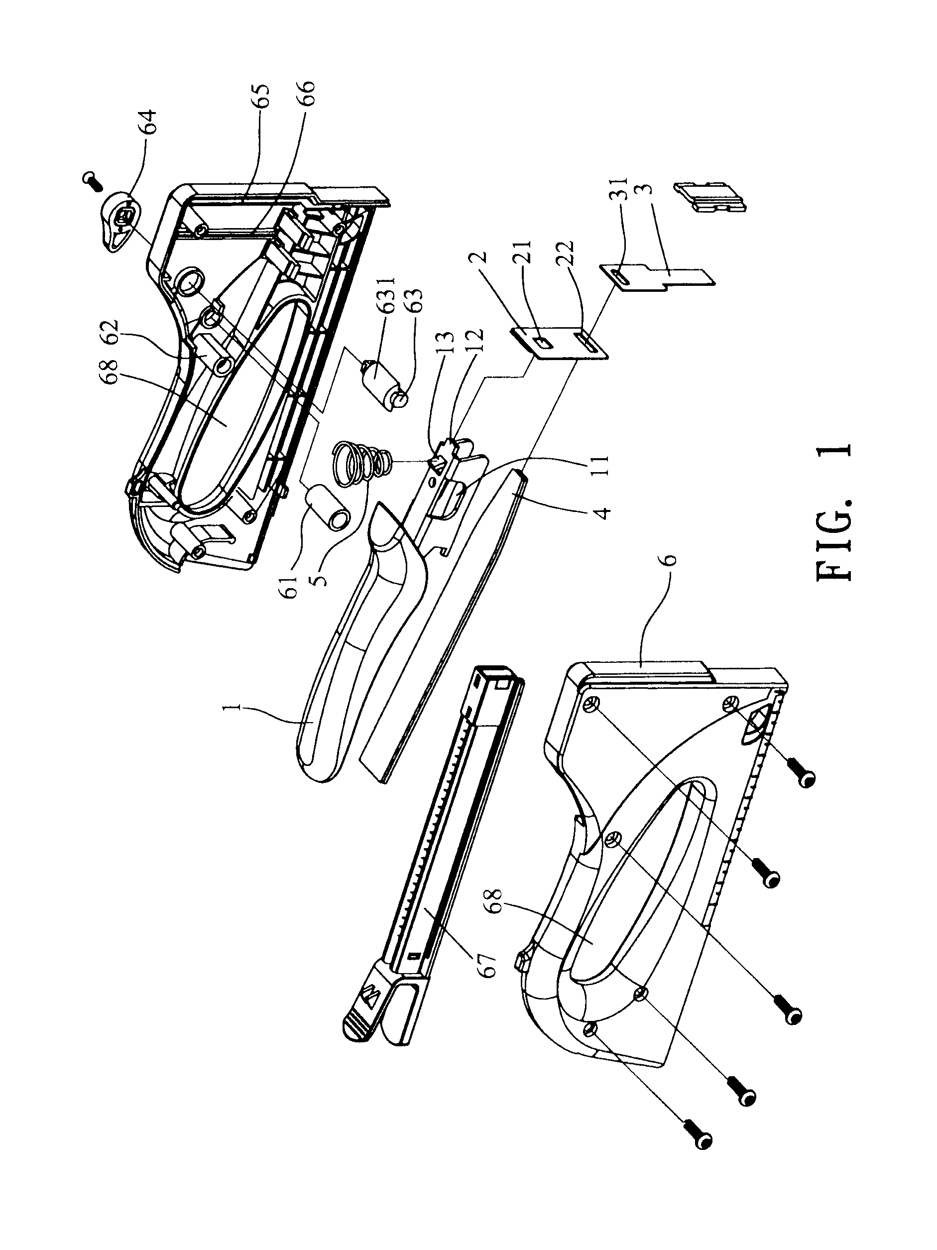
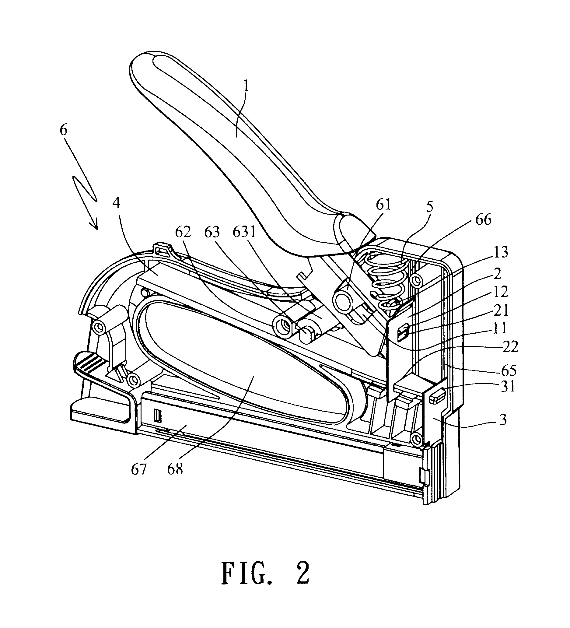
[0014]Referring to FIGS. 1 and 2, the staple gun of the present invention comprises an arm 1 which has an elongate hole 11 defined in a first end thereof and a protrusion 12 extends from the first end of the arm 1. A top block 13 is located on the top of the first end of the arm 1.

[0015]A driving plate 2 has a first hole 21 and a second hole 22 which is located below the first hole 21. The protrusion 12 of the arm 1 is inserted into the first hole 21.

[0016]A strike plate 3 is located beside (in front of) the driving plate 2 and has a third hole 31.

[0017]A resilient plate 4 has a first end extending through the second hole 22 of the driving plate 2 and the third hole 31 of the strike plate 3.

[0018]A spring 5 is rested on the top block 13 on the top of the first end of the arm 1.

[0019]A case 6 includes a fulcrum axle 61, a fixed axle 62, an adjustment axle 63, an adjustment knob 64, a first slot 65, a second slot 66, a magazine 67, and a holding hole 68. The fulcrum axle 61 extends th...


PUM


Abstract

A staple gun includes an arm having an elongate hole and a protrusion extends from the first end of the arm. A driving plate has a first hole and a second hole. The protrusion is inserted into the first hole. A strike plate is located beside the driving plate and has a third hole. A resilient plate has a first end extending through the second hole and the third hole. A spring is rested on a top of the first end of the arm. A case includes a fulcrum axle and a fixed axle. The fulcrum axle extends through the elongate hole of the arm and is located behind the driving plate. The fixed axle contacts a top surface of the resilient plate. The effort arm from the fulcrum axle to the front end of the arm is shortened so as to save effort when pivoting the arm.

Description

FIELD OF THE INVENTION[0001]The present invention relates to a staple gun, and more particularly, to a staple gun using lever principle to generate a significant force to staple the documents and to save the user's effort.BACKGROUND OF THE INVENTION[0002]A conventional staple gun 7 is shown in FIG. 6 and generally includes case 71 in which a holding hole 711 is defined so that the users can hold the staple gun 7 by the holding hole 711. A magazine 712 is connected to the underside of the case 71 and staples are received in the magazine 712. The case 71 has a slot 72 defined in a front end thereof and a strike plate 73 is located in the slot 72. A resilient plate 74 is located in the case 71 and the front end of the resilient plate 74 is engaged with the strike plate 73. A Fixed axle 75 of the case 71 extends through an arm 76 which is pivotably connected to the front end of the case 71. The front end of the arm 76 is hooked to the strike plate 73 and a spring 78 is located between t...

Claims


Application Information

Patent Timeline
IPC IPC(8): B25C5/11
CPCB25C5/11
Inventor HUANG, CHIEN CHUAN
Owner HUANG CHIEN CHUAN
Learn More