Adhesive and release liner application system

a technology of adhesive and release liner, applied in the direction of girders, joints, nailing tools, etc., can solve the problem of difficult operation of machines

Active Publication Date: 2019-10-31
NAT LUMBER CO
View PDF0 Cites 5 Cited by
  • Summary
  • Abstract
  • Description
  • Claims
  • Application Information

AI Technical Summary

Benefits of technology

[0005]Featured is an improved adhesive and release liner application system. The preferred system better ensures the release liner is adequately applied over the adhesive on a

Problems solved by technology

In some cases, that machine is difficult to operate and failed in some instan

Method used


Image

  • Adhesive and release liner application system
  • Adhesive and release liner application system
  • Adhesive and release liner application system

Examples


Embodiment Construction

[0019]Aside from the preferred embodiment or embodiments disclosed below, this invention is capable of other embodiments and of being practiced or being carried out in various ways. Thus, it is to be understood that the invention is not limited in its application to the details of construction and the arrangements of components set forth in the following description or illustrated in the drawings. If only one embodiment is described herein, the claims hereof are not to be limited to that embodiment. Moreover, the claims hereof are not to be read restrictively unless there is clear and convincing evidence manifesting a certain exclusion, restriction, or disclaimer.

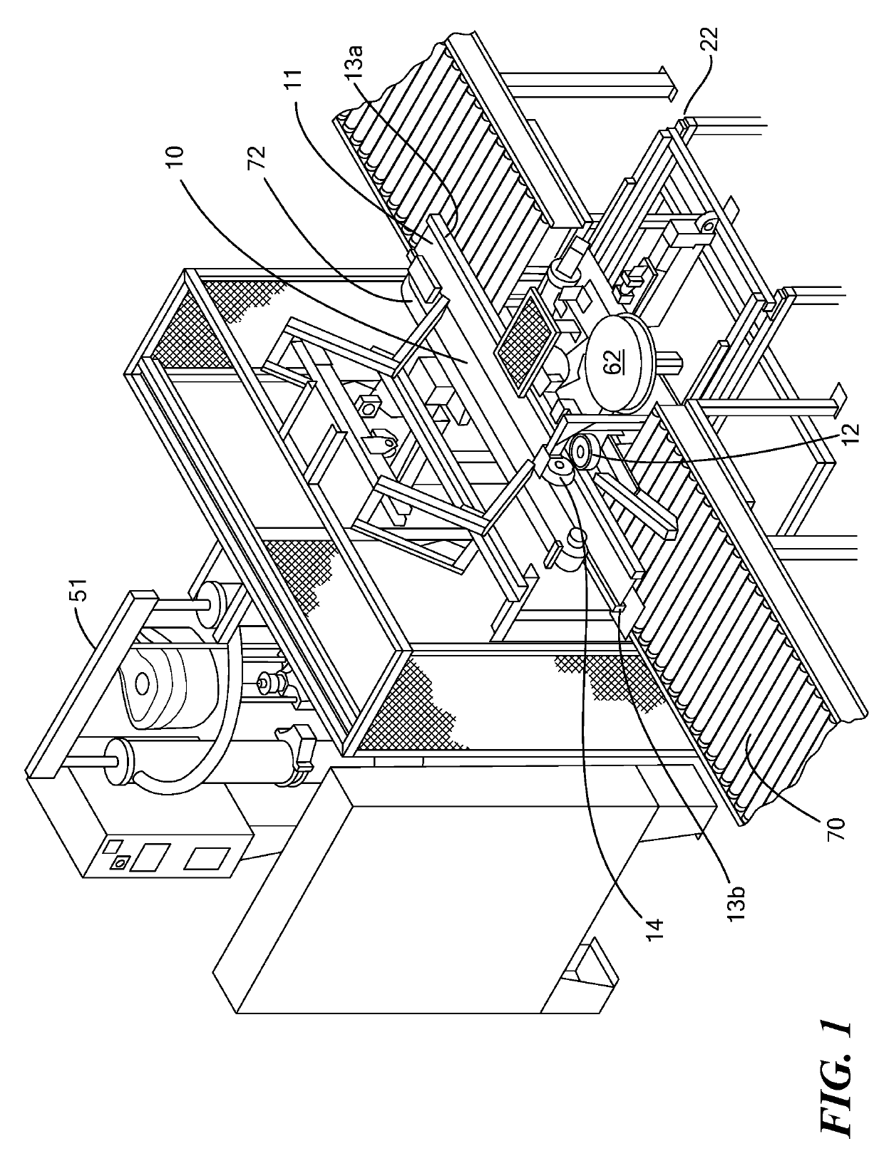
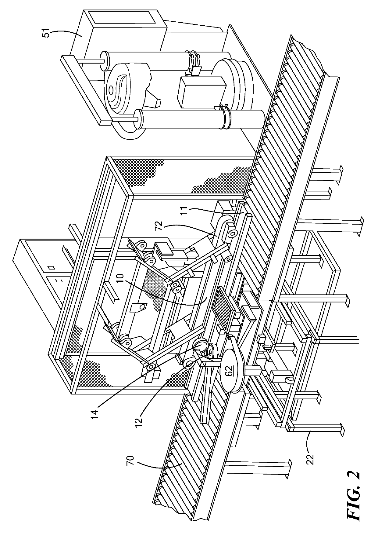
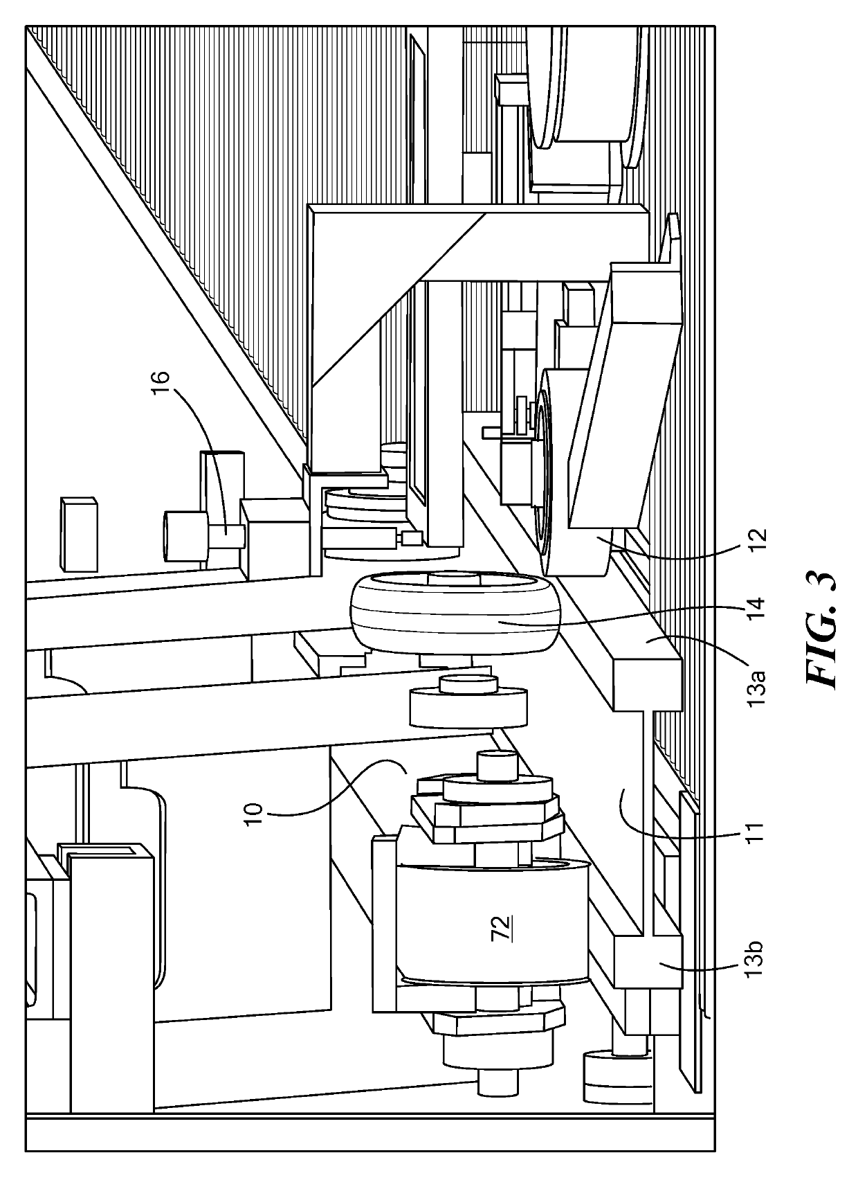
[0020]In one design as shown in FIGS. 1-5 a cut I-joist 11 proceeds out of a saw substation along a conveyor 70 and to a station where the adhesive and release liner (film) are applied to the outer face of flange 13a. The I-joist may he purchased from Boise Cascade.

[0021]One preferred station includes an overhead actuated b...


PUM


Abstract

An adhesive and release liner application system and method. A bottom table is slidable with respect to a frame and a middle table is slidable with respect to the bottom table. An elevator drive subsystem between a top table and the middle table is configured to adjust the elevation of the top table relative to the middle table. An adhesive head, connected to an adhesive supply subsystem, a release liner applicator, a release liner cutter, and a staple gun are mounted to the top table for applying the adhesive to a surface of a structural member positioned adjacent the top table, for applying a release liner over the adhesive on the surface, for inserting at least one staple through the release liner and into the surface, and for cutting the release liner.

Description

RELATED APPLICATIONS[0001]This application claims benefit of and priority to U.S. Provisional Application Ser. No. 62 / 662,309 filed Apr. 25, 2018, under 35 U.S.C. §§ 119, 120, 363, 365, and 37 C.F.R. § 1.55 and § 1.78, which is incorporated herein by this reference.FIELD OF THE INVENTION[0002]This subject invention relates to a system which applies a layer of adhesive and release liner to I-joists and other building elements and engineered wood products.BACKGROUND OF THE INVENTION[0003]When workers deploy I-joists and other engineered wood products as structural components in buildings, the workers often manually apply adhesive to the top flange of the I-joist and then secure subflooring or other materials to the I-joist. See U.S. published Patent Application No. 2006 / 0101785 and U.S. Pat. Nos. 5,254,203 and 6,263,636 all incorporated herein by this reference.[0004]In U.S. Pat. Nos. 7,918,960 and 8,915,280, both also incorporated herein by this reference, a very specific machine is ...

Claims


Application Information

Patent Timeline
IPC IPC(8): B27M3/00B05D5/10B05D7/06B05C5/00B05C11/00B27F7/36B27G11/00
CPCB05C5/002B05D5/10B27G11/00B27M3/0026F16B11/006E04C3/02B27F7/36B05C11/00B05D7/06E04C3/14B05C5/0204
Inventor MARTIN, BROCKLYNBURKHOLDER, JANSENBOGUSH, PETERBRUCE, DAVIDTHOMPSON, ROBERTVANBUSKIRK, PAUL J.CAMACHO, STEVENETZEL, MICHAEL J.BENNETT, DEREK DANIEL
Owner NAT LUMBER CO
Why Eureka
Try Eureka