

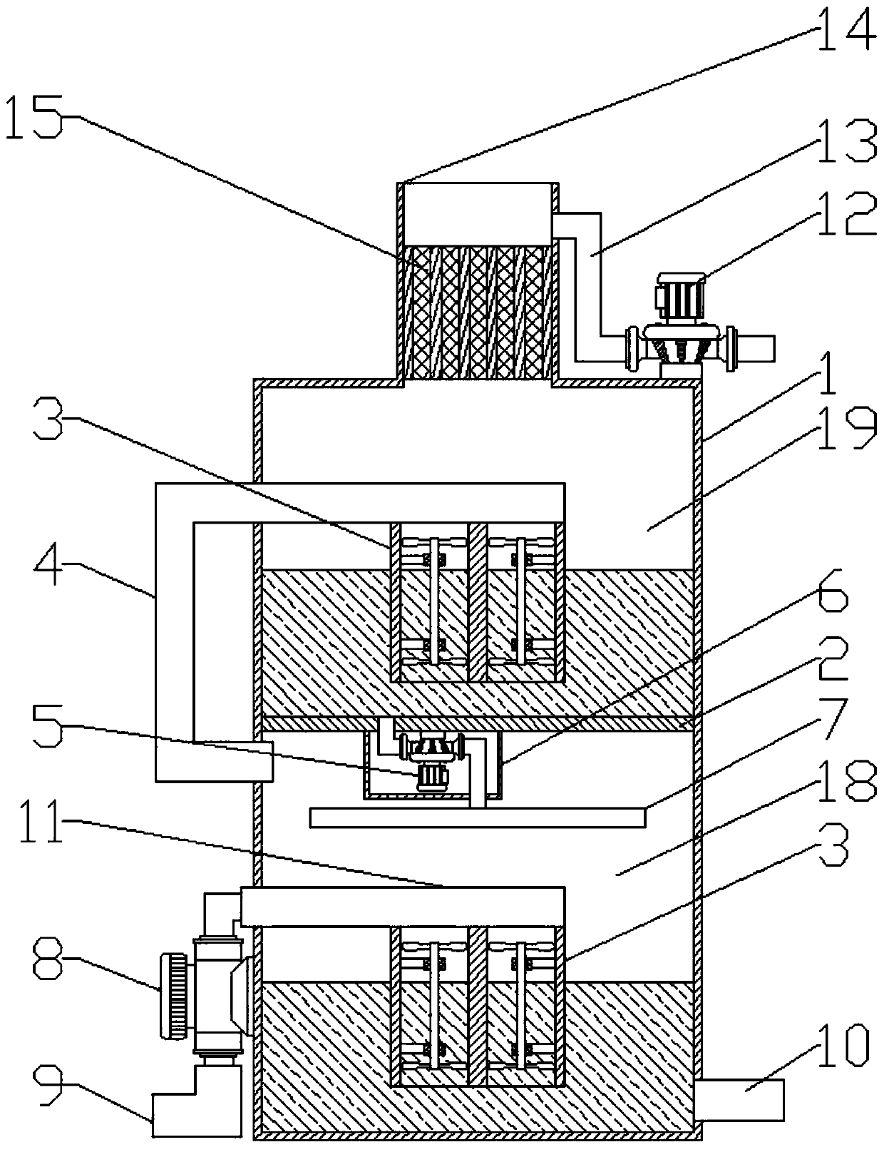
Smoke treatment equipment
A flue gas treatment and equipment technology, applied in the direction of gas treatment, dispersed particle separation, membrane technology, etc., can solve the problems of increased consumption of alkaline solution, low efficiency of sulfur dioxide absorption, insufficient contact between flue gas and alkaline solution, etc. Achieve the effects of improving desulfurization effect, high desulfurization degree and slowing down the passing time
- Summary
- Abstract
- Description
- Claims
- Application Information
AI Technical Summary
Problems solved by technology
Method used
Image

Examples
Embodiment Construction
[0017] In order to make the object, technical solution and advantages of the present invention clearer, the present invention will be described in further detail below in conjunction with specific embodiments and with reference to the accompanying drawings.
[0018] It should be noted that all expressions using "first" and "second" in the embodiments of the present invention are to distinguish two entities with the same name but different parameters or parameters that are not the same, see "first" and "second" It is only for the convenience of expression, and should not be understood as limiting the embodiments of the present invention. In addition, the terms of direction and position mentioned in the present invention, such as "upper", "middle", "lower", "front", "rear", "Left", "right", "inner", "outer", "side", etc., are only referring to the directions and positions of the attached drawings. Therefore, the terms of directions and positions used are for explaining and unders...
PUM
 Abstract
Description
Claims
Application Information