

System for secure variable data rate transmission
- Summary
- Abstract
- Description
- Claims
- Application Information
AI Technical Summary
Benefits of technology
Problems solved by technology
Method used
Image

Examples
Embodiment Construction
[0028]Modern digital communication networks suffer from the ability of malicious attackers eavesdropping on all digital communications. To prevent eavesdropping on private digital communications across public communication media / networks, encryption technology is used to secure the transmission media. Additionally, modern systems employ variable data rate (VDR) transmissions. Traditional secure transmissions rely on fixed length transmissions but modern variable length transmissions require a new method for implementing security.
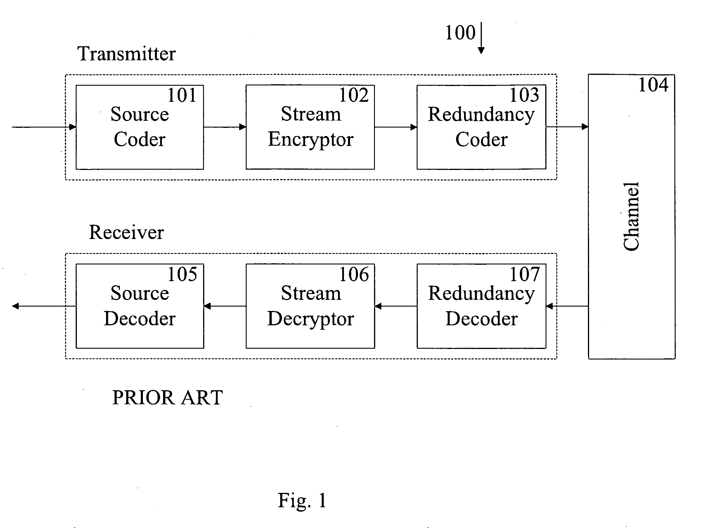
[0029]A typical secure variable data rate transceiver is shown in FIG. 1 by circuit 100. This consists of a source coder, stream encryptor, and redundancy coder on the transmitter side. The source coder is responsible for converting the constant data rate (CDR) information bits into variable data rate (VDR) information bits. The stream encryptor encrypts the VDR bits using a stream cipher to generate an encrypted VDR stream. The redundancy coder adds redunda...
PUM
 Abstract
Description
Claims
Application Information