

Rapid-flow and smooth-spouted container lid
a container lid and smooth-spouted technology, applied in the field of containers, can solve the problems of sacrificing precious time in the race, reducing concentration and efficiency, and a large amount of fluid splashing and spilling
- Summary
- Abstract
- Description
- Claims
- Application Information
AI Technical Summary
Benefits of technology
Problems solved by technology
Method used
Image


Examples
first embodiment
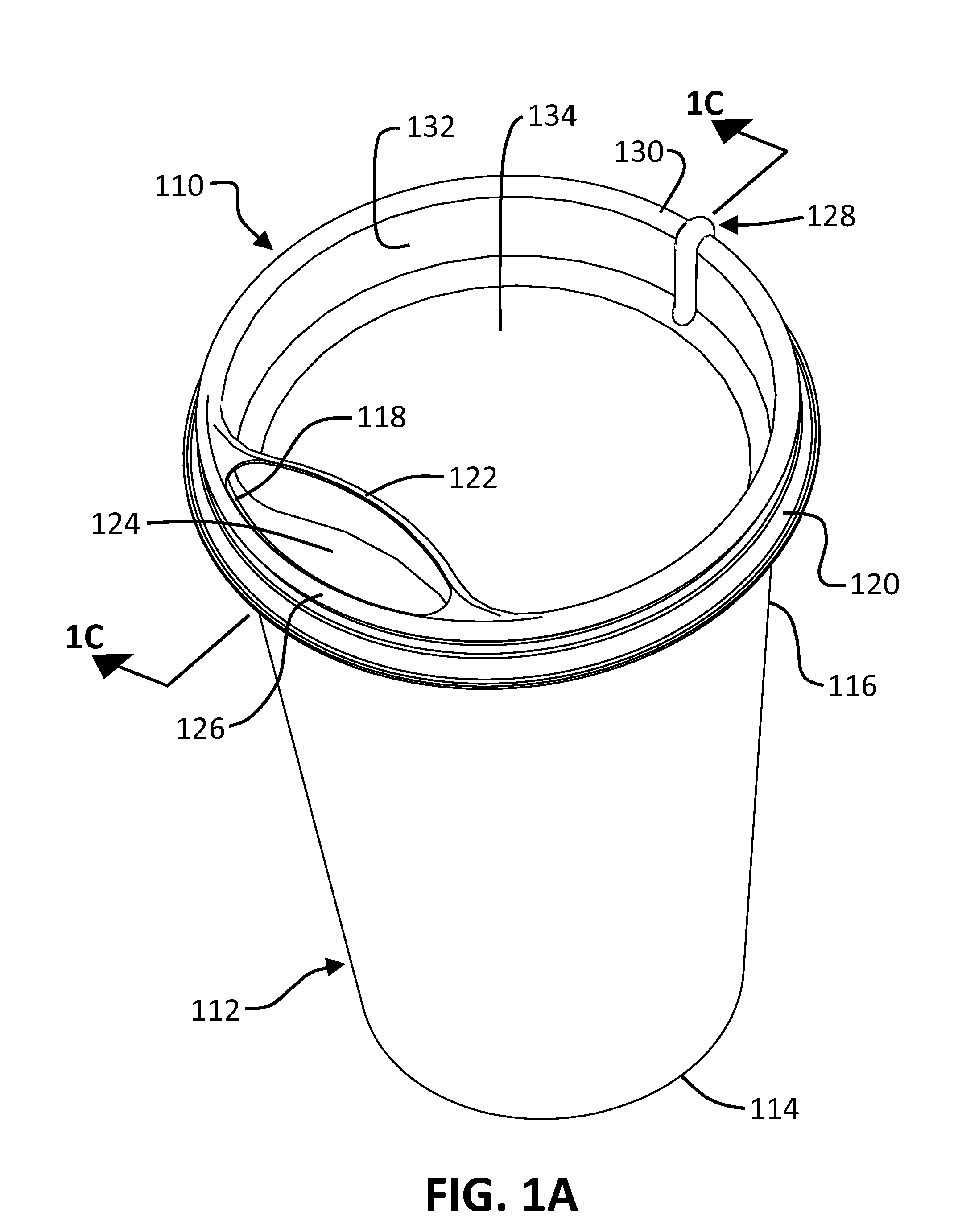
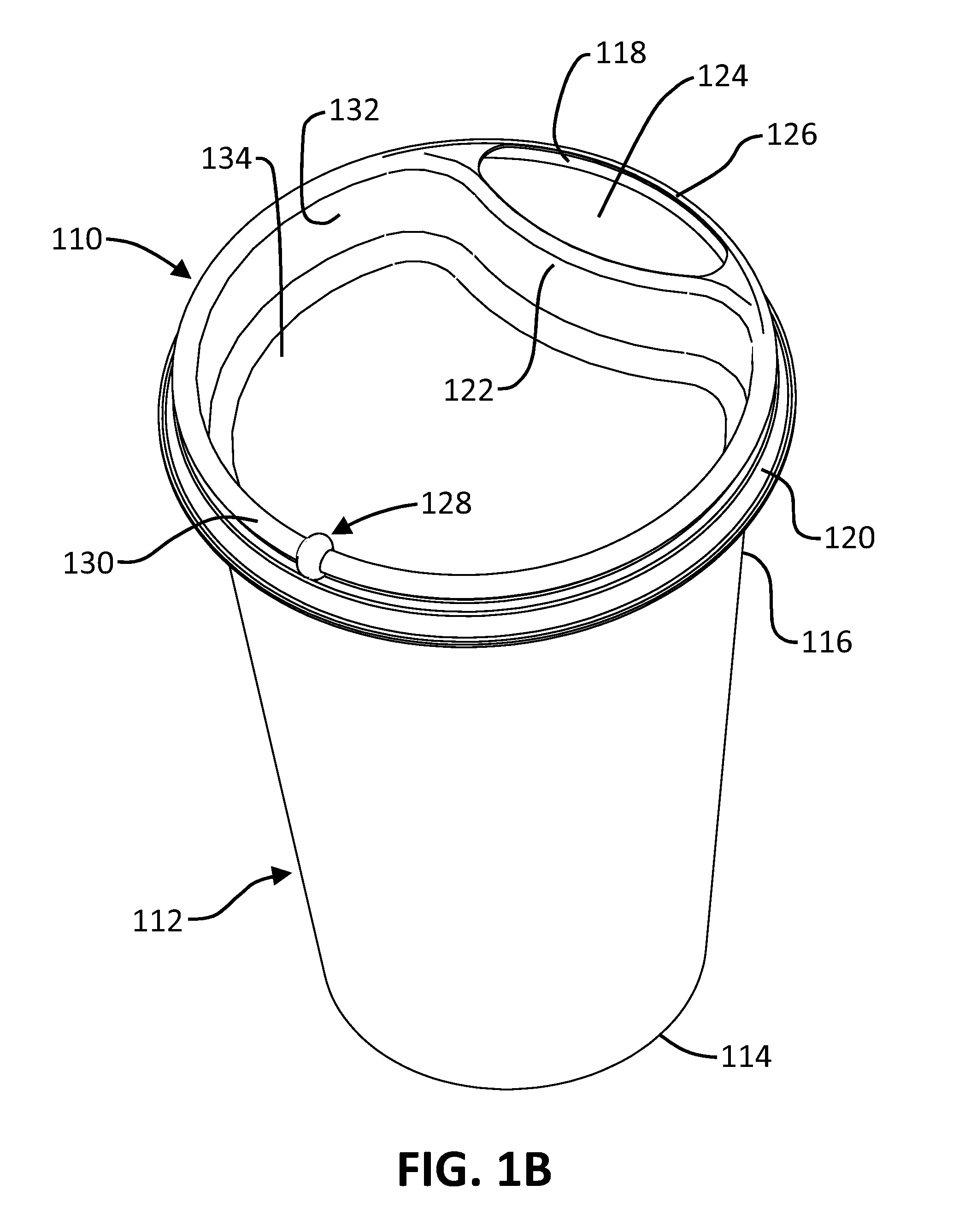
[0037]FIGS. 1A and 1B are perspective views of a container cap, closure, cover, or lid 110 and a cup, can, or container 112 having a bottom 114 and an open end 116. The lid 110 is shown attached to the container 112 at a lip or rim 118 of the open end 116 of the container 112 by means of an annular clamp or mounting skirt 120. The illustrated mounting skirt 120 is of the type typically incorporated into durable or disposable drink-through or pour-through lids, and is adapted to be press-fit onto the open end of a cup, can, or container and held in place by means of friction or snapped onto the open end of a cup, can, or container and held in place by means of a mechanical interlock. The structure of the mounting skirt may take any form without departing from the scope of the present invention, provided that it is suitable for securing the lid 110 to a durable or disposable container. The lid 110 itself may also be either durable or disposable.
[0038]The lid 110 comprises a mouthpiece...
second embodiment
[0043]FIGS. 2A and 2B are perspective views of a lid 210 and the container 112. The lid 210 is shown attached to the container 112 at the open end 116 of the container 112 by means of a mounting skirt 220. The lid 210 comprises a smooth spout 222 with a content discharge opening 224 located at the center of the lid 210 and a vent opening 228 located at the top of the mounting skirt 220. The lid 210 further includes a sidewall 232 that is generally located adjacent to the inside portion of the open end 116 of the container 112 and a recess 234 that is generally located between the smooth spout 222 and the sidewall 232. The lid 210 itself may be either durable or disposable.
[0044]FIG. 2C is a cross-sectional view of the second embodiment taken along line 2C-2C of FIG. 2A. FIG. 2D is a cross-sectional view of the second embodiment taken along line 2D-2D of FIG. 2B. FIGS. 2C and 2D provide more detailed illustrations of the mounting skirt 220 and the vent opening 228 of the lid 210. A r...
third embodiment
[0048]FIGS. 3A and 3B are perspective views of a lid 310 and the container 112. The lid 310 is shown attached to the container 112 at the open end 116 of the container 112 by means of a mounting skirt 320. The lid 310 comprises a smooth spout 322 with a content discharge opening 324 located at a proximal end 326 and a vent opening 328 located at a distal end 330. The distal end 330 of the lid 310 refers to the portion farthest away from the user when drinking through the lid 310, whereas the proximal end 326 refers to the portion of the lid 310 facing the user when drinking, generally adjacent to the smooth spout 322. The lid 310 itself may be either durable or disposable.
[0049]FIG. 3C is a cross-sectional view of the third embodiment taken along line 3C-3C of FIG. 3A. FIG. 3C provides more detailed illustrations of the mounting skirt 320 and the vent opening 328 of the lid 310. A retention feature 336 of the mounting skirt 320 ensures that the lid 310 remains attached to the contai...
PUM
| Property | Measurement | Unit |
|---|---|---|
| Flow rate | aaaaa | aaaaa |
| Content | aaaaa | aaaaa |
Abstract
Description
Claims
Application Information