Circuit board of portable electronic device

Inactive Publication Date: 2012-02-02
HON HAI PRECISION IND CO LTD
View PDF9 Cites 3 Cited by
  • Summary
  • Abstract
  • Description
  • Claims
  • Application Information

AI Technical Summary

Problems solved by technology

Processing many different shaped circuit boards, which will receive similar circuits, is very inefficient and labor consuming.

Method used


Image

  • Circuit board of portable electronic device
  • Circuit board of portable electronic device
  • Circuit board of portable electronic device

Examples


Embodiment Construction

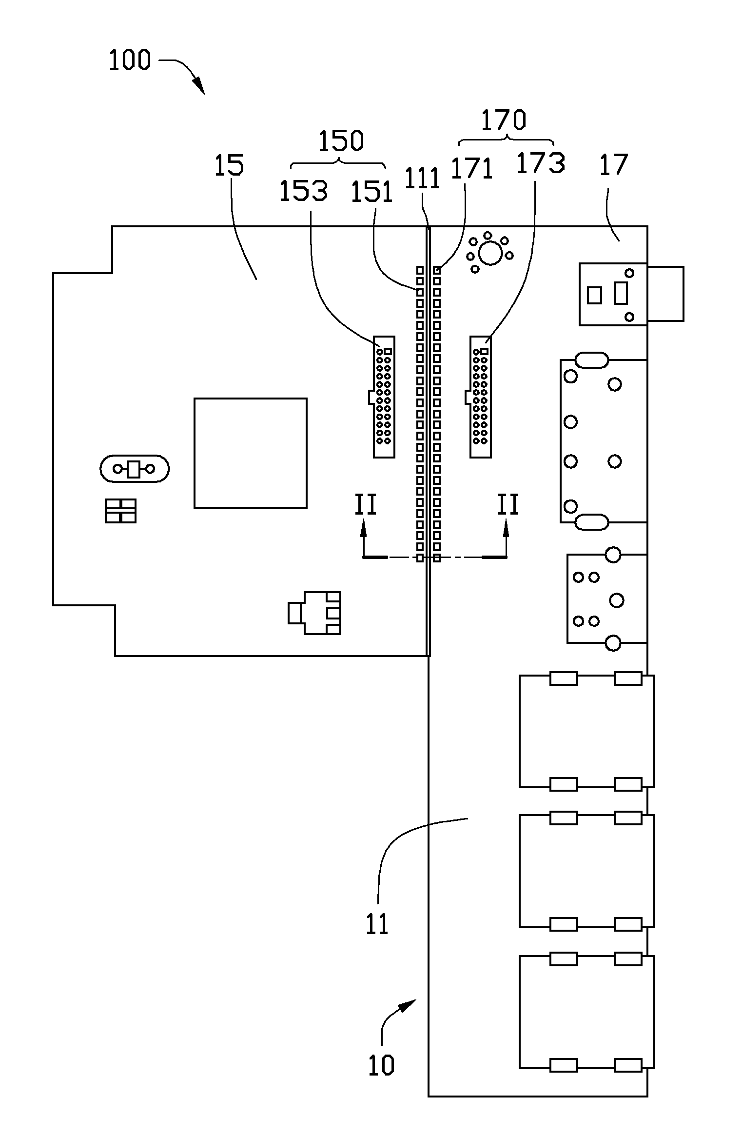
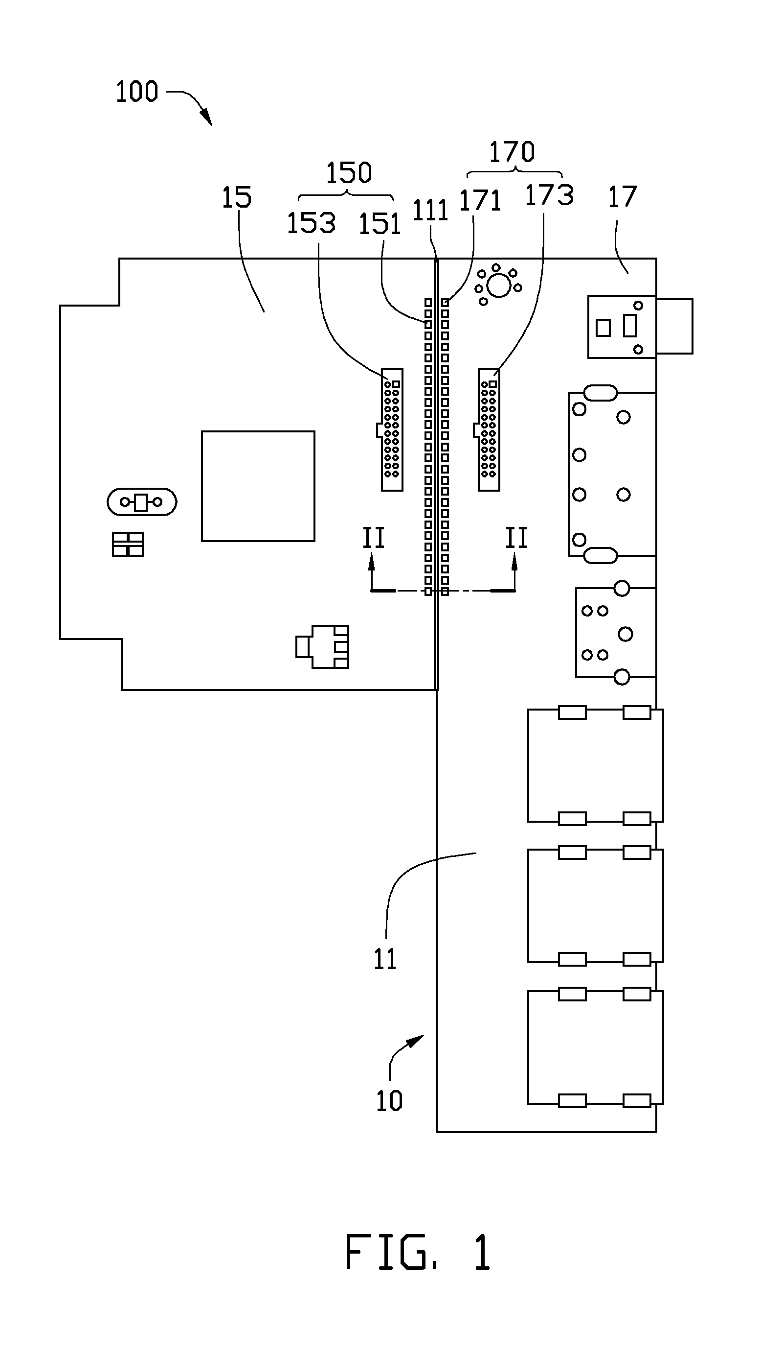
[0013]FIG. 1 shows a circuit board 100, according to an exemplary embodiment, in a first state. The circuit board 100 can be used in a portable electronic device, such as a mobile phone, a personal digital assistant (PDA), or MP3 / MP4 players. The circuit board 100 includes a main body 10, which is a panel including circuits of the portable electronic device. In the first state, the circuit board 100 maintains an original shape and is received in a housing of a portable electronic device (not shown), a size similar to the original size of the main body 10.

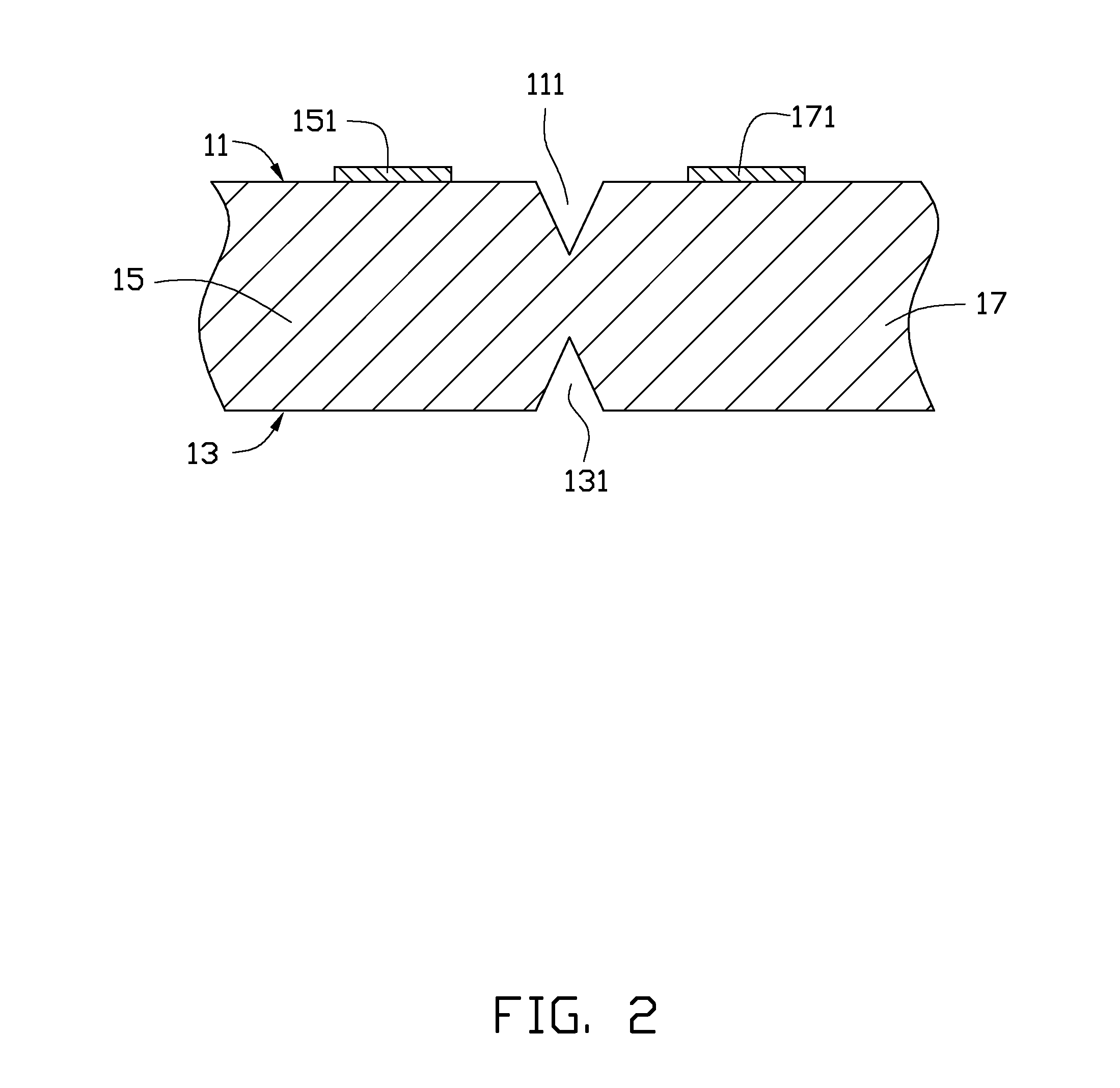
[0014]Also referring to FIG. 2, the main body 10 has a first surface 11 and a second surface 13, and the first surface 11 and the second surface 13 are opposite and parallel to each other. The main body 10 defines a first separating groove 111 in the first surface 11 and a second separating groove 131 in the second surface 13, and thus is divided into a first segment 15 and a second segment 17 by the first separating groove 111 and ...


PUM


Abstract

A circuit board includes a main body and a connecting member mounted on the main body. The main body defines a separating groove and is divided into two segments by the separating groove, such that the main body is broken along the separating groove to separate the two segments from each other when a force is applied thereto. When the main body is broken along the separating groove to separate the two segments from each other, the connecting member electronically connects the two segments to each other.

Description

BACKGROUND[0001]1. Technical Field[0002]The present disclosure relates to circuit boards for portable electronic devices, and particularly to a circuit board capable of having different shapes.[0003]2. Description of Related Art[0004]Portable electronic devices, such as mobile phones, personal digital assistants (PDA), and laptop computers, are widely used. Portable electronic devices include housings and circuit boards received in the housings. The circuit boards are usually processed to be shaped similar to the shape of its housing so they can be received in the housing. Portable electronic devices can have housings in many different shapes, but may need to use similar circuits. Thus, the circuit boards of the portable electronic devices need to be mechanically processed to fit the different shapes of the different shaped housings but still be able to receive the circuits for general use in many portable electronic devices. Processing many different shaped circuit boards, which wi...

Claims


Application Information

Patent Timeline
IPC IPC(8): H01R12/16
CPCH01R12/732H05K1/0286H05K1/144H05K1/147H05K2201/10189H05K3/368H05K2201/042H05K2201/0909H05K2201/10022H05K3/0052
Inventor HSU, MING-YUAN
Owner HON HAI PRECISION IND CO LTD
Why Eureka
Try Eureka