Apparatus and method for a tunable multi-mode multi-band power amplifier module

a power amplifier module and multi-band technology, applied in the direction of high-frequency amplifiers, gated amplifiers, gain control, etc., can solve the problems of significant size and cost impact on the overall wireless handset design, semiconductor power transistor devices can only efficiently transmit rf signals in a single mode and a single band, and compromises are often made for one mod

Active Publication Date: 2012-03-08
SAMSUNG ELECTRONICS CO LTD
View PDF4 Cites 22 Cited by
  • Summary
  • Abstract
  • Description
  • Claims
  • Application Information

AI Technical Summary

Problems solved by technology

Having five complete discrete power amplifier circuits as in this example has a significant size and cost impact on the overall wireless handset design.
Using fixed matching networks, a semiconductor power transistor device can only efficiently transmit RF signals in a single mode and a single band.
While some power amplifiers may be operated in two modes which have similar bands, compromises are often made for one mode or both modes due to different modulation schemes.
Further, the GSM and CDMA modes present challenges because the GSM system the power amplifier transistor operates in saturated region, whereas in CDMA the transistor has to operate at a more linear region in continuous time.
Thus, a single fixed matching network cannot usually provide optimum matching for all potential frequency bands simultaneously.
The ever decreasing form factor and ever increasing functionality demanded of wireless terminals creates conflicting challenges on front-end devices like number of PAs that can be installed.
Currently, board space constrains limits the number of PAs on even the most complicated handset units.
Despite much effort within the industry to aggressively reduce device sizes, the fundamental physics and fabrication challenges prohibit the device size shrink to keep pace with the number of added functions within the wireless handset.
Not only do additional PA devices cost more board space, the peripheral passive components around each PA device also occupy board space and increase proportionately with the number of PAs used.
However, fixed matching networks may prevent full utilization of these solutions.

Method used


Image

  • Apparatus and method for a tunable multi-mode multi-band power amplifier module
  • Apparatus and method for a tunable multi-mode multi-band power amplifier module
  • Apparatus and method for a tunable multi-mode multi-band power amplifier module

Examples


Embodiment Construction

[0026]FIGS. 1 through 9, discussed below, and the various embodiments used to describe the principles of the present disclosure in this patent document are by way of illustration only and should not be construed in any way to limit the scope of the disclosure. Those skilled in the art will understand that the principles of the present disclosure may be implemented in any suitably arranged mobile station.

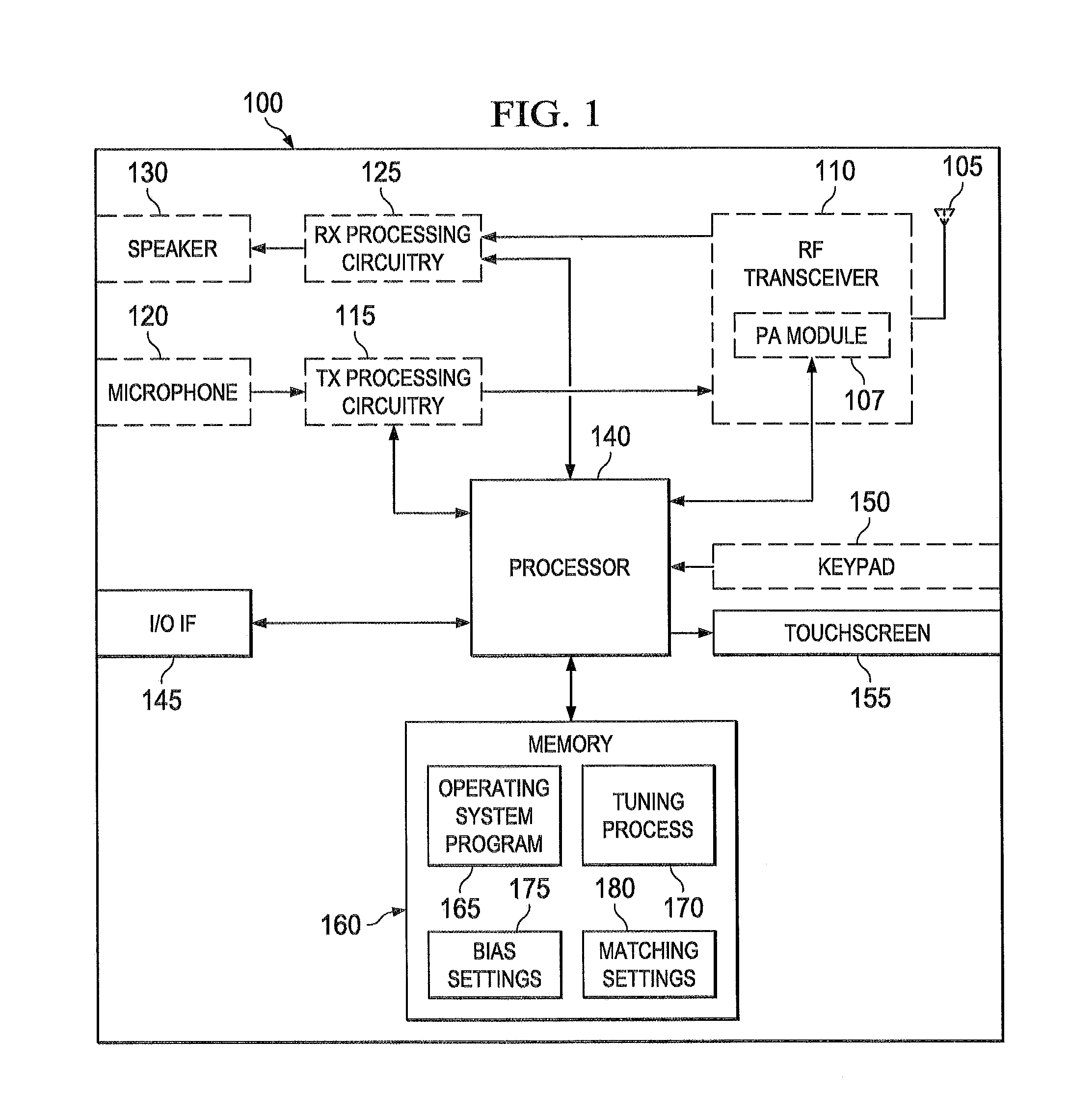
[0027]FIG. 1 illustrates a wireless mobile station according to the present disclosure. Mobile station 100 comprises antenna 105, PA module 107, radio frequency (RF) transceiver 110, transmit (TX) processing circuitry 115, microphone 120, and receive (RX) processing circuitry 125. Mobile station 100 also comprises speaker 130, processor 140, input / output (I / O) interface (IF) 145, keypad 150, touchscreen 155, and memory 160. Memory 160 further comprises basic operating system process 165, tuning process 170, bias settings 175, and matching settings 180. In these examples, mobile stati...


PUM


Abstract

An apparatus and method amplify a signal for use in a wireless network. The apparatus includes a power amplifier, an envelope modulator, a tunable matching network (TMN), and a controller. The power amplifier outputs the signal at an output power. The envelope modulator controls a bias setting for the power amplifier. The TMN includes a plurality of immittance elements. The controller is operably connected the envelope modulator and the TMN. The controller identifies a desired value for the output power of the power amplifier, controls the output power of the power amplifier by modifying the bias setting of the power amplifier, and sets a number of the plurality of immittance elements based on the bias setting of the power amplifier.

Description

CROSS-REFERENCE TO RELATED APPLICATION(S) AND CLAIM OF PRIORITY[0001]The present application is related to U.S. Provisional Patent Application No. 61 / 379,695, filed Sep. 2, 2010, entitled “SMART TUNABLE MULTI MODE MULTI BAND POWER AMPLIFIER MODULE”. Provisional Patent Application No. 61 / 379,695 is assigned to the assignee of the present application and is hereby incorporated by reference into the present application as if fully set forth herein. The present application hereby claims priority under 35 U.S.C. §119(e) to U.S. Provisional Patent Application No. 61 / 379,695.[0002]The present application is also related to U.S. patent application Ser. No. 13 / 214,892, filed on Aug. 22, 2011, and entitled “APPARATUS AND METHOD FOR CONTROLLING A TUNABLE MATCHING NETWORK IN A WIRELESS NETWORK”. U.S. patent application Ser. No. 13 / 214,892 is assigned to the assignee of the present application and is hereby incorporated by reference into the present application as if fully set forth herein.TECHN...

Claims


Application Information

Patent Timeline
Patent Type & Authority Applications(United States)
IPC IPC(8): H03F3/04H03F3/19H03G3/20
CPCH03F1/0233H03F1/0261H03F1/0277H03F3/19H03F1/14H03F2203/7231H03F2203/7239H03G3/3042H03F3/72H03F1/30H03F3/24H04B1/04
Inventor ZHU, XUBROBSTON, MICHAELLOH, LUP M.
Owner SAMSUNG ELECTRONICS CO LTD
Why Eureka
Try Eureka