Printed material, method of producing printed material, and printer

a printing method and printing technology, applied in the field of printed materials, can solve the problems of difficult alignment of a plurality of images on a front surface and a plurality of images on a back surface, and achieve the effect of preventing or suppressing undulation of a first image layer

Active Publication Date: 2012-03-29
DAINIPPON SCREEN MTG CO LTD
View PDF19 Cites 22 Cited by
  • Summary
  • Abstract
  • Description
  • Claims
  • Application Information

AI Technical Summary

Benefits of technology

[0005]The present invention is intended for a printed material in which images can be visually recognized from both sides thereof, and it is an object of the present invention to prevent or suppress undulation of a first image layer from being visually recognized from a side of a second image layer.

Problems solved by technology

For this reason, it is not possible to produce a printed material with high efficiency.
Further, when it is intended to print images on both sides of a web-like base member, it is difficult to perform alignment of a plurality of images on a front surface and a plurality of images on a back surface.

Method used


Image

  • Printed material, method of producing printed material, and printer
  • Printed material, method of producing printed material, and printer
  • Printed material, method of producing printed material, and printer

Examples


Embodiment Construction

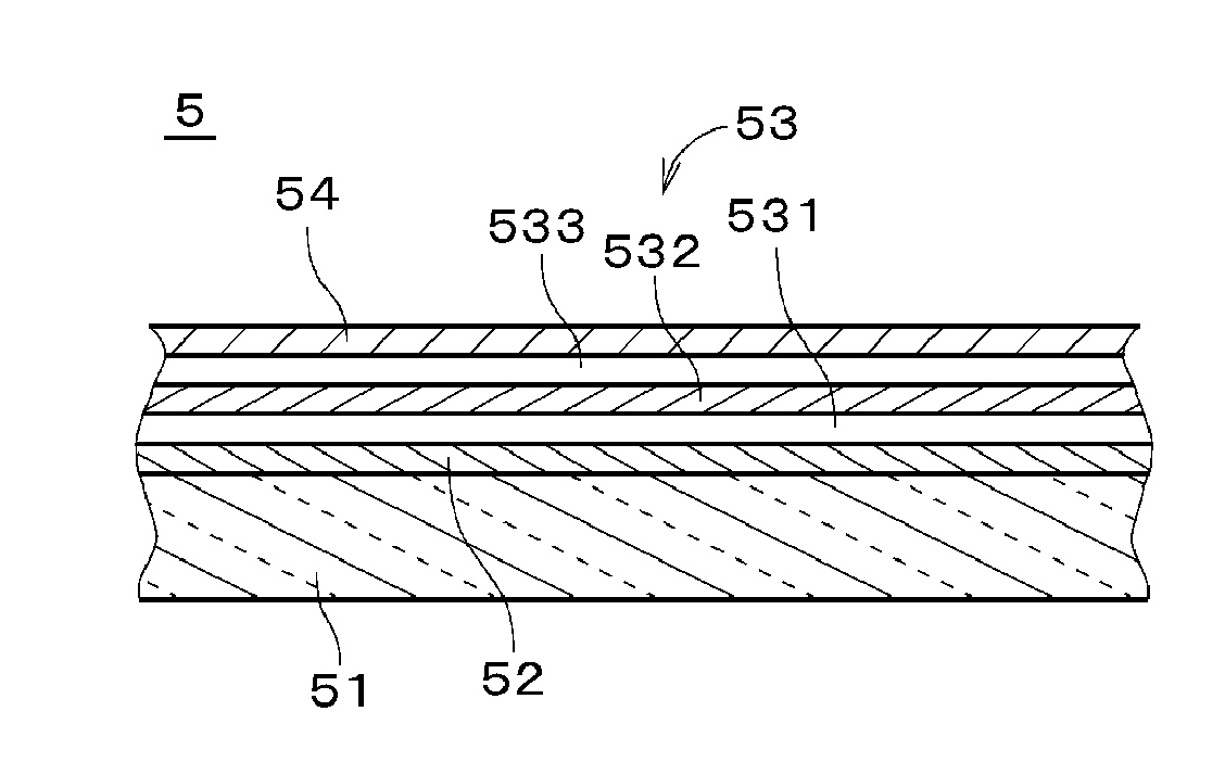
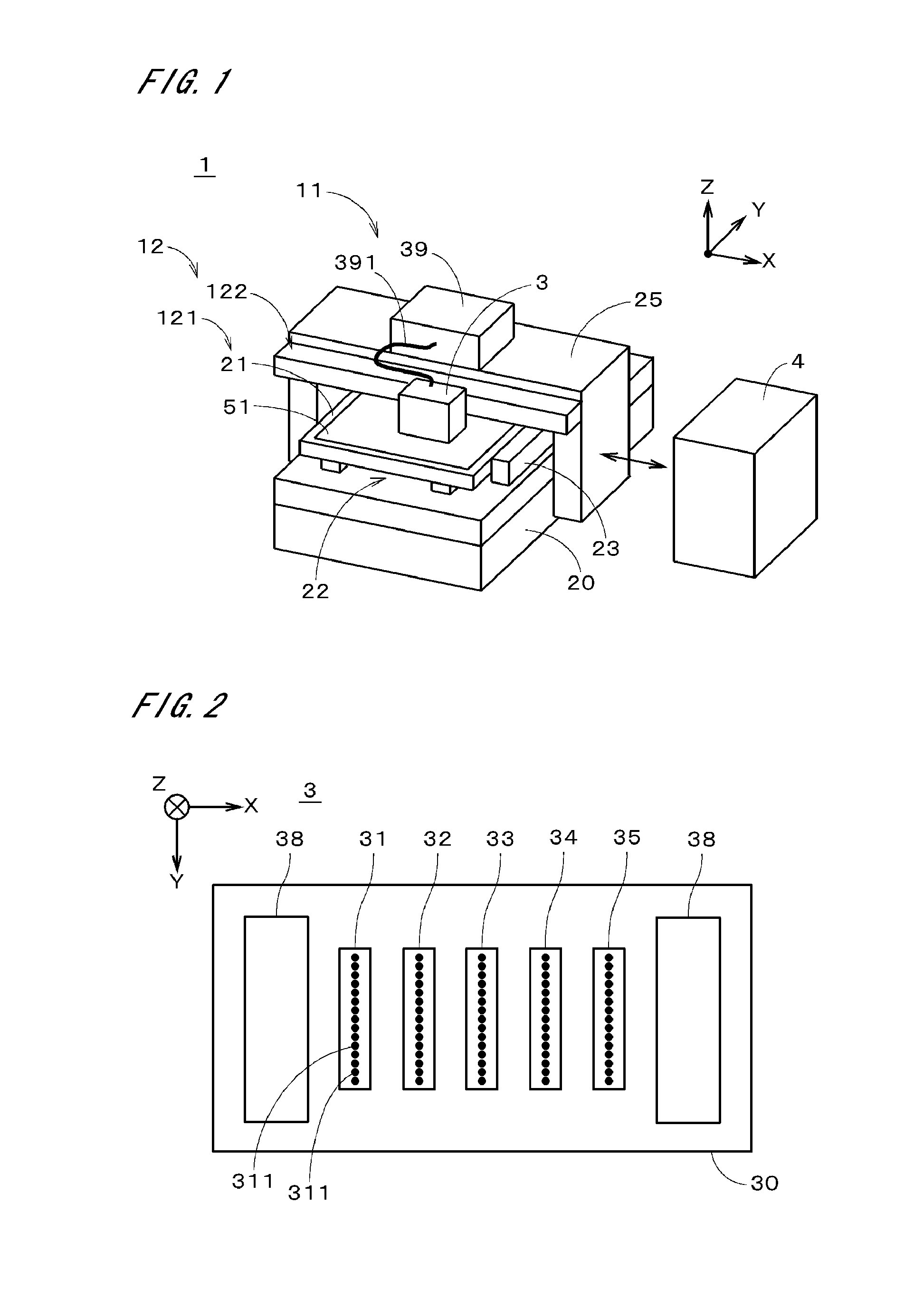
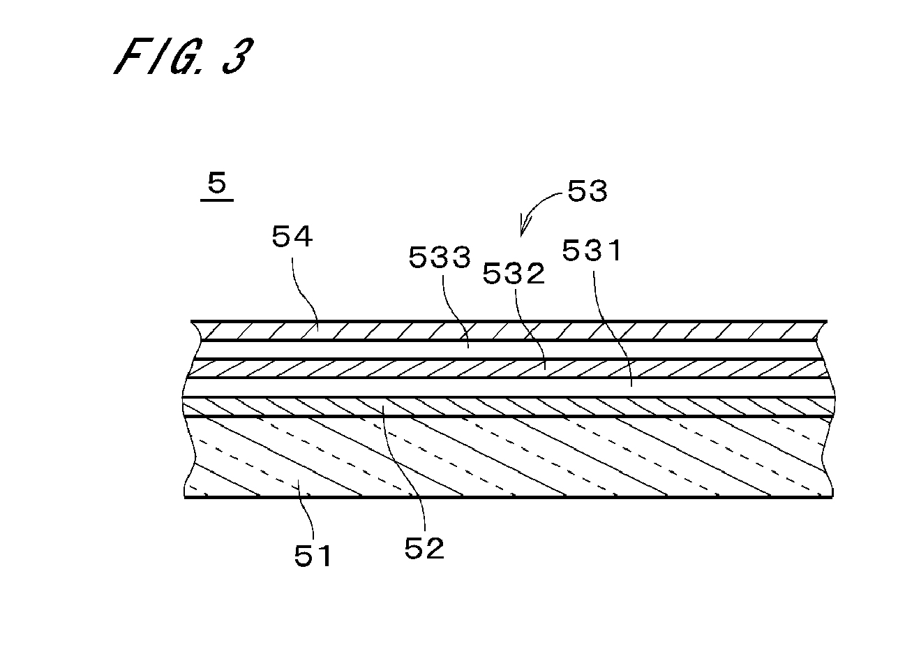
[0034]FIG. 1 is a perspective view showing an appearance of a printer 1 in accordance with the first preferred embodiment of the present invention. The printer 1 produces a printed material by printing an image on, for example, a film-like or plate-like transparent base member 51 formed of a resin, by ink jet method. Hereinafter, the transparent base member 51 is referred to simply as a “base member 51”.

[0035]The printer 1 comprises an image forming part 11, a base member feeding mechanism 121, a head moving mechanism 122, and a controller 4. The controller 4 controls the image forming part 11, the base member feeding mechanism 121, and the head moving mechanism 122. The image forming part 11 comprises a head unit 3 for discharging droplets of ink toward a main surface (hereinafter, referred to as a “recording surface”) on a (+Z) side of the base member 51 and a light source 39 for emitting ultraviolet rays. In FIG. 1, an X direction, a Y direction, and a Z direction are orthogonal ...


PUM

PropertyMeasurementUnit
transparentaaaaaaaaaa

Abstract

A printed material (5) has a transparent base member (51), a first image layer (52) formed on the base member, an intermediate layer (53) formed on the first image layer, and a second image layer (54) formed on the intermediate layer. The intermediate layer has a lower white background layer (531) positioned above the first image layer, a light blocking layer (532) positioned above the lower white background layer, and an upper white background layer (533) positioned above the light blocking layer. In the printed material, a thickness of the light blocking layer is uneven in conformity with undulation of the first image layer, and therefore a surface of the intermediate layer which is in contact with the second image layer is flat. With this structure, it is possible to prevent or suppress the undulation of the first image layer from appearing in the second image layer.

Description

TECHNICAL FIELD[0001]The present invention relates to a printed material whose image can be visually recognized from both sides, a method of producing the printed material, and a printer.BACKGROUND ART[0002]Conventionally, printed materials in each of which images are printed on both sides of a base member have been widely used for advertisements, decorations, and the like. In a process of printing images on a front surface and a back surface of the base member, normally, after an image is printed on one of the surfaces, the base member is reversed and another image is printed on the other surface. For this reason, it is not possible to produce a printed material with high efficiency. Further, when it is intended to print images on both sides of a web-like base member, it is difficult to perform alignment of a plurality of images on a front surface and a plurality of images on a back surface.[0003]Then, proposed is a technique in which two images are printed to be stacked on one of ...

Claims


Application Information

Patent Timeline
Patent Type & Authority Applications(United States)
IPC IPC(8): B32B3/10B41J29/38B41J2/01
CPCB41M3/008Y10T428/24868B41M5/0064B41M5/0047B41J2/2117B41J3/407B41J11/00214B41J11/0015B41J13/0009
Inventor NAKANO, MASAYUKIMORIWAKI, KAZUSHI
Owner DAINIPPON SCREEN MTG CO LTD
Why Eureka
Try Eureka