Damper and process thereof

a technology of adamant and a process, applied in the field of adamant, can solve the problems of difficult to cause stable chemical surface treatment, large amount of unevenness in the metal surface subjected to no chemical surface treatment, and insufficient adhesive power

Inactive Publication Date: 2008-04-08
FUKOKU CO LTD
View PDF14 Cites 4 Cited by
  • Summary
  • Abstract
  • Description
  • Claims
  • Application Information

AI Technical Summary

Benefits of technology

[0016]Regarding a surface facing and being providing with the polymer elastic body in the hub or the inertia mass body, and a surface facing and being providing with the hub or the inertia mass body in the polymer elastic body, reactive groups existing between the one metal surface of the polymer elastic body and the organosilane on the surface of the polymer elastic body easily react with the organosilane, so that chemical adhesive mechanism is created and thereby adhesive power therebetween is obtained. On the other hand, as there is no chemical surface treatment between the other metal surface of the hub and the inertia mass body and the organosilane, the other metal surface being without performing chemical surface treatment easily generates rust or the like thereon, so that it is difficult to cause stable chemical surface treatment and thereby to obtain sufficient adhesive power. It is however presumed that sufficient physical adhesive mechanism to compensate for the chemical adhesive mechanism is formed between the above-mentioned metal surface and the organosilane and thereby sufficient adhesive power is caused.
[0018]Thus, in this physical adhesive mechanism, the adhesive power becomes larger as the surface roughness of the metal surface becomes larger. However, if the surface roughness becomes too large, the polymer elastic body can not adapt the unevenness of the metal surface. Therefore, the organosilane put between the polymer elastic body and the metal surface becomes very uneven in thickness, so that an effective area for being capable of generating effective adhesive power is reduced. Thus, the adhesive power drops. To increase the adhesive power in strength, the surface roughness of the metal surface is performed by machining or the like. If the surface roughness is within a range of 5 to 50 μmRz (JIS B0601) at ten-points average roughness, stable and strong adhesive power thereof can be obtained, so that the range is particular preferable.
[0021]In the damper of the present invention, since the organosilane is put between the polymer elastic body and the metal surface, the physical adhesive mechanism is formed therebetween as described above. When the damper is used, even if high torque is irregularly applied to the damper to cause a slip between the polymer elastic body and the metal surface, function of the physical adhesive mechanism can be restored to some degree in comparison with a bond between the polymer elastic body and the metal surface. Therefore, there is a low possibility that all the functions of the physical adhesive mechanism are lost at once by input of excessive torque. It is considered that this is because even if the uneven surface in the fitted state is somewhat slid, the uneven surface is fitted to the organosilane again, to some extent, at the slid position.

Problems solved by technology

On the other hand, as there is no chemical surface treatment between the other metal surface of the hub and the inertia mass body and the organosilane, the other metal surface being without performing chemical surface treatment easily generates rust or the like thereon, so that it is difficult to cause stable chemical surface treatment and thereby to obtain sufficient adhesive power.
It can be considered that from a microscopic viewpoint, a great deal of unevenness is generated in the metal surface subjected to no chemical surface treatment.

Method used


Image

  • Damper and process thereof
  • Damper and process thereof
  • Damper and process thereof

Examples


Embodiment Construction

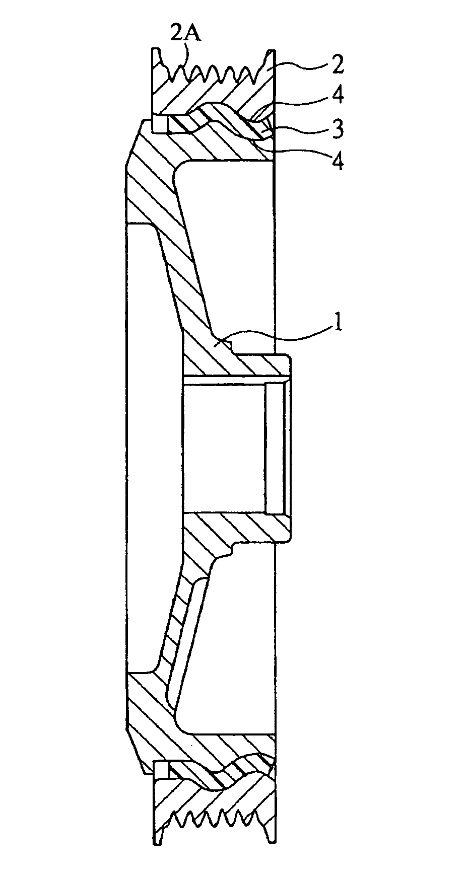
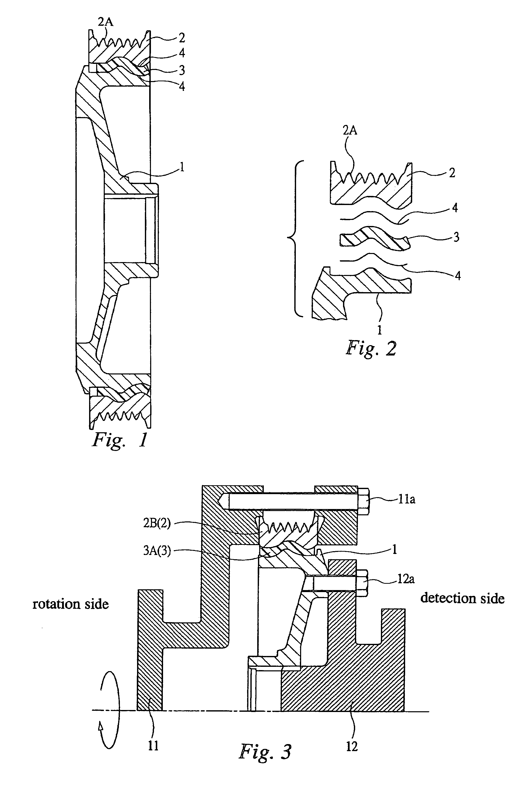
[0031]FIG. 1 is a cross section showing an embodiment of a fitting type damper according to the present invention.

[0032]FIG. 2 is a partially cross section of the damper shown in FIG. 1. In these drawings, reference number 1 denotes a hub. This hub 1 is made of a given metal and has a ring form. The hub 1 is attached to an outer periphery of an end of a crankshaft (not shown) in an internal combustion engine such as an automobile engine or the like. A metal surface of the outer periphery of the hub 1 is subjected to no chemical surface treatment such as plating treatment.

[0033]Reference number 2 denotes a inertia mass body, and this inertia mass body 2 is made of a given metal and has a ring form. The inertia mass body 2 is arranged at an outer peripheral side of the hub 1 and concentrically with the hub 1 and is spaced from the hub 1. A metal surface of an inner periphery of the inertia mass body 2 is not subjected to chemical surface treatment such as plating treatment or the like...


PUM

PropertyMeasurementUnit
outer diameteraaaaaaaaaa
temperatureaaaaaaaaaa
heightaaaaaaaaaa

Abstract

A fitting type damper and a process thereof being capable of increasing largely slipping torque in strength are ones that the large slipping torque can be increased not only when the damper is a new product but also after a heat aging test and / or a durability test are performed. And, the damper is one that γ-mercaptopropyltrimethoxysilane 4, which is an organosilane used as a non-slip agent, is adhered and fitted between a hub 1 formed by some metal parts and a rubber elastic body 3, and between a inertia mass body 2 formed by some metal parts and the rubber elastic body 3.

Description

[0001]This application is a Divisional Application of U.S. Ser. No. 09 / 936,538 entitled ‘Damper and Process Thereof’, Seiichi Tagawa, et al., filed on Sep. 13, 2001 now U.S. Pat. No. 6,984,432, and claims the benefit of the filing date thereof under 35 U.S.C. § 120.TECHNICAL FIELD[0002]The present invention relates to a damper, and in particular to a torsional damper that absorbs twisting vibration generated in a rotation driving system such as a crankshaft of an internal combustion engine.BACKGROUND ART[0003]As this type damper, the followings have been hitherto suggested: (1) an adhesion type damper wherein a rubber elastic body is vulcanized and adhered between a sleeve and a inertia mass body and a hub is press-fitted inside the sleeve; (2) an adhesion type damper wherein, after an adhesive agent is applied to both surfaces of the a sleeve and a inertia mass body, a vulcanized and molded rubber elastic body is press-fitted between the hub and the inertia mass body; (3) an adhesi...

Claims


Application Information

Patent Timeline
Patent Type & Authority Patents(United States)
IPC IPC(8): B32B3/02F16F15/126F16H55/36
CPCF16F15/126F16F2226/02F16F2226/042F16H55/36F16H2055/366Y10T428/24413Y10T428/12049Y10T74/2131Y10T428/24405Y10T428/24355Y10T428/21Y10T428/12562Y10T428/12Y10T428/31663Y10T428/31696
Inventor TAGAWA, SEIICHIOGAWA, MIKIHITO
Owner FUKOKU CO LTD
Why Eureka
Try Eureka