Heavy-duty axle-to-beam connection

a technology of axle and beam, which is applied in the direction of transportation and packaging, paper/cardboard containers, manufacturing tools, etc., can solve the problems of causing significant stress risers and local mechanical property changes in the axle, and reducing the life expectancy of the axle,

Active Publication Date: 2012-04-05
HENDRICKSON USA L L C
View PDF13 Cites 31 Cited by
  • Summary
  • Abstract
  • Description
  • Claims
  • Application Information

AI Technical Summary

Benefits of technology

[0013]Objectives of the present invention include providing a heavy-duty vehicle axle-to beam connection that eliminates welds on the axle of the axle / suspension system.

Problems solved by technology

The welding of the axle sleeve directly to the axle, at the sleeve windows, can potentially create significant stress risers and local mechanical property changes in the axle, as is generally well known in the art.
These stress risers and local mechanical property changes in the axle can in turn potentially reduce the life expectancy of the axle.
However, these mechanically fastened axle-to-beam connection variants are often heavier than the welded variants and often require re-torque of the mechanical fasteners.
In addition, increasing axle wall thickness also can undesirably increase weight.

Method used


Image

  • Heavy-duty axle-to-beam connection
  • Heavy-duty axle-to-beam connection
  • Heavy-duty axle-to-beam connection

Examples


Embodiment Construction

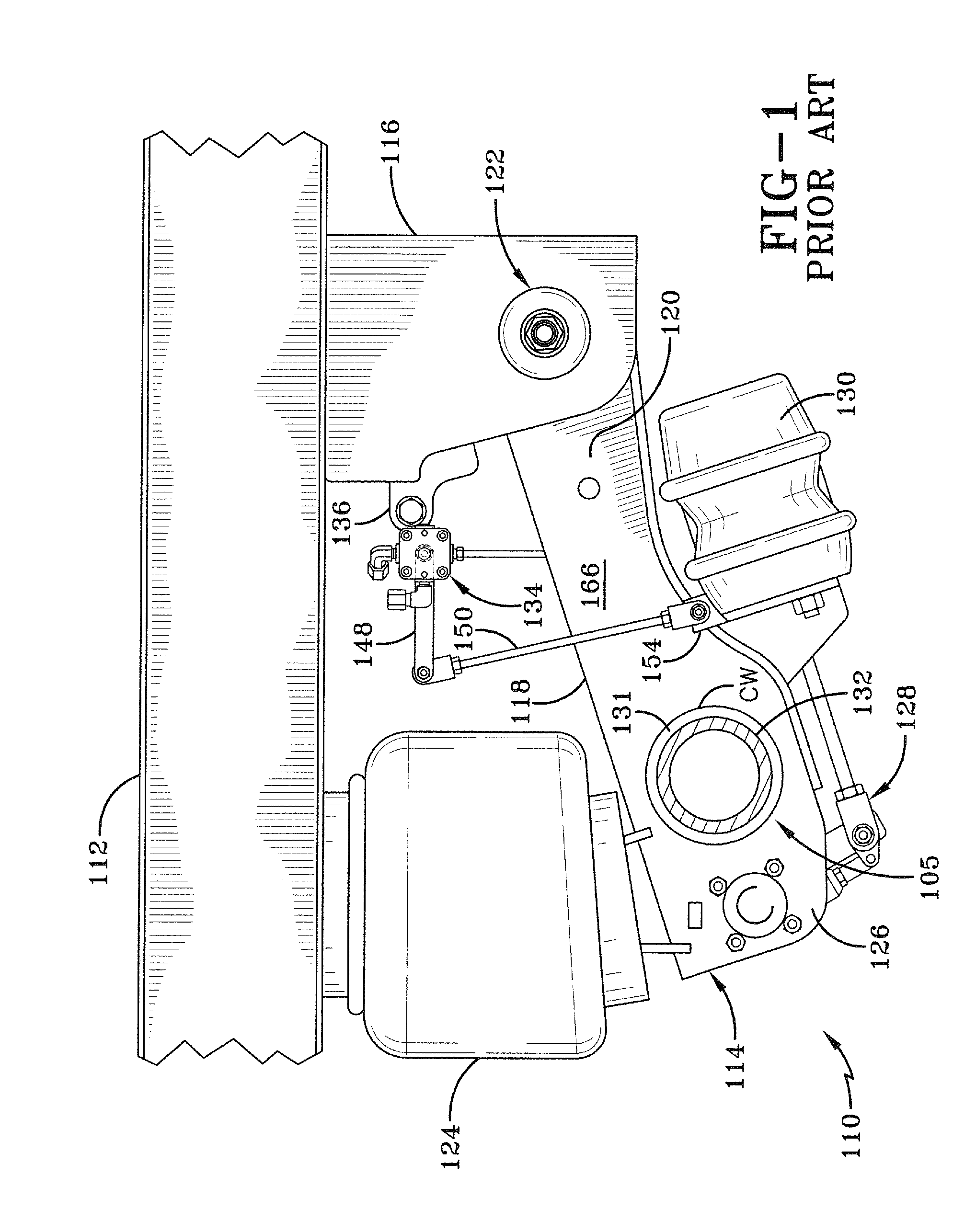
[0050]A prior art trailing arm overslung beam-type air-ride axle / suspension system is indicated generally at 110, is shown in FIG. 1 mounted on a main member 112 of a heavy-duty vehicle (not shown), and now will be described.

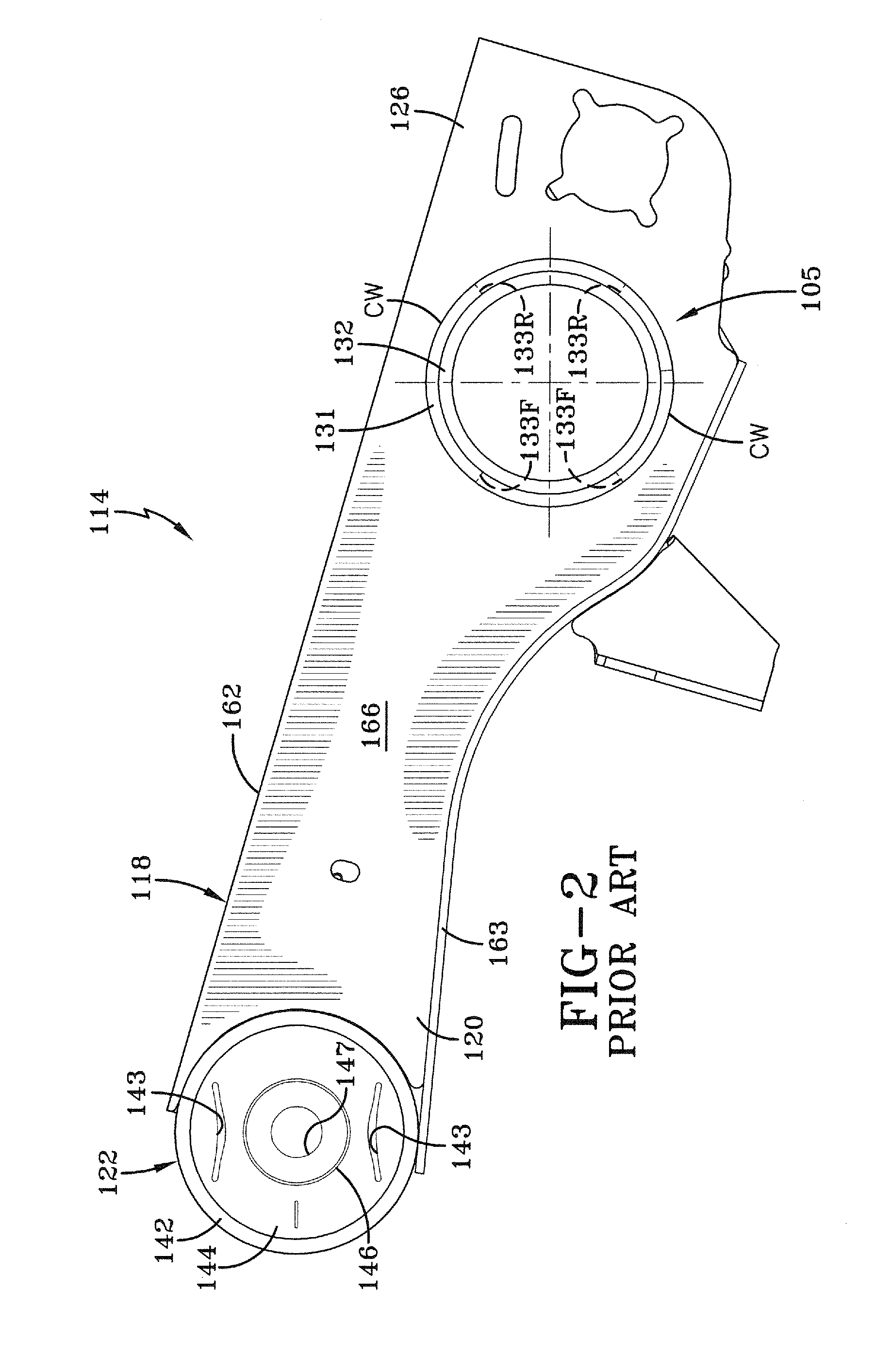
[0051]It should be noted that main member 112 is generally representative of various types of frames used for heavy-duty vehicles, including primary frames that do not support a subframe and primary frames and / or floor structures that do support a subframe. For primary frames and / or floor structures that do support a subframe, the subframe can be non-movable or movable, the latter being commonly referred to as a slider box. For the purpose of convenience, main member 112 is shown in FIG. 1 as a primary frame. Moreover, because axle / suspension system 110 includes a pair of suspension assemblies 114 (only one of which is shown in FIG. 1) that generally mirror one another, for sake of clarity only one of the suspension assemblies will be described below.

[0052]Suspe...


PUM

PropertyMeasurementUnit
shapeaaaaaaaaaa
plasticityaaaaaaaaaa
mechanical propertyaaaaaaaaaa

Abstract

An axle-to-beam connection for a vehicle axle/suspension system includes an axle having at least one depression formed therein. A sleeve is formed with at least one depression and disposed about the axle so that the axle depression and the sleeve depression matingly engage one another to form a mated pair of depressions. A method of forming the axle-to-beam connection includes providing an axle and disposing a sleeve about the axle. At least one mated pair of depressions is simultaneously formed in the axle and the sleeve. The sleeve is immovably mounted to a vehicle axle/suspension system.

Description

CROSS REFERENCE TO RELATED APPLICATION[0001]This application claims the benefit of U.S. Provisional Patent Application Ser. No. 61 / 388,276, filed Sep. 30, 2010.BACKGROUND OF THE INVENTION[0002]1. Field of the Invention[0003]The invention relates to vehicle axle / suspension systems, and in particular to the suspension assemblies of those systems which are useful for heavy-duty vehicles such as trucks and tractor-trailers. More particularly, the invention is directed to a heavy-duty trailing or leading aim axle / suspension system for trucks and tractor-trailers, in which the axle is securely and efficiently connected to the beams by an improved axle sleeve and axle structure at the axle-to-beam connection. The improved axle sleeve and axle structure, together with the manner in which the axle-to-beam connection is made and assembled, eliminates welds on the axle. Elimination of the welds on the axle in turn eliminates stress risers and localized mechanical property changes in the axle c...

Claims


Application Information

Patent Timeline
Patent Type & Authority Applications(United States)
IPC IPC(8): B60G9/00B32B37/12B23P11/00
CPCB23P11/00Y10T29/49908B60B2900/321B60B2900/325B60G9/003B60G2200/31B60G2204/4306B60G2206/8201B60Y2200/14B60G5/03B60G2200/318B60G2206/821B60G11/113B60G11/465B60G2206/32B60G2206/8209Y10T156/10Y10T29/49826B60B35/005F16D51/00F16D2051/003
Inventor WESTNEDGE, ANDREW J.RUBALSKIY, DMITRIY E.KEELER, MICHAEL J.PIERCE, PHILLIPPI R.
Owner HENDRICKSON USA L L C
Why Eureka
Try Eureka