Modular rack system with gussetless joints

a module and rack technology, applied in the field of vehicle equipment, can solve the problems of unacceptably large structure, added shipping costs, and difficult shipping,

Active Publication Date: 2014-10-16
THULE INC
View PDF15 Cites 7 Cited by
  • Summary
  • Abstract
  • Description
  • Claims
  • Application Information

AI Technical Summary

Benefits of technology

[0011]The present invention preserves the advantages of prior art rack systems, such as those used in vehicles. In addition, it provides new advantages not found in currently available systems and overcomes many disadvantages of such currently available systems.
[0013]Therefore, an object of the present invention is to provide a modular rack system that eliminates welds to increase manufacturing capacity by removing the tedious welding process.
[0017]Another object of the present invention is to provide a modular rack system that is devoid of any welding to reduce the overall costs of production of the rack system.

Problems solved by technology

Although the prior art systems function acceptably as rack systems, they suffer from a number of disadvantages that make them undesirable.
For example, a base horizontal member 14, a vertical upright member 16 and top saddle 18 are typically welded together, which results in a structure that is unacceptably large in size, which makes shipping very difficult because a large box must be used.
This oversize packaging adds costs to shipping and, as a result, adds to the cost of the rack system.
Also, such a prior art structure is very labor intensive because parts must be welded together.
Such welding requires expensive parts and components and is a time consuming and expensive manufacturing process.
Missed weld locations will also make the rack “non functional” out of the box forcing customer to return the product.
Moreover, welded products add weight to the overall package thereby adding cost and, unfortunately, welds, best seen as 26 in FIG. 4, are susceptible to failure over time.
If there is a failure, it is very difficult and expensive to replace only a portion of the entire welded structure.
So, as a result, wasteful replacement of the entire welded unitary structure is typically required.
These braces 12 add cost and further increase manufacturing time thereby further adding to the overall costs of production.
Thus, such a permanently welded structure makes it more difficult to provide options and flexibility for the user.
As a result, prior art rack systems 10 are not conducive to a desirable modular rack system.

Method used


Image

  • Modular rack system with gussetless joints
  • Modular rack system with gussetless joints
  • Modular rack system with gussetless joints

Examples


Embodiment Construction

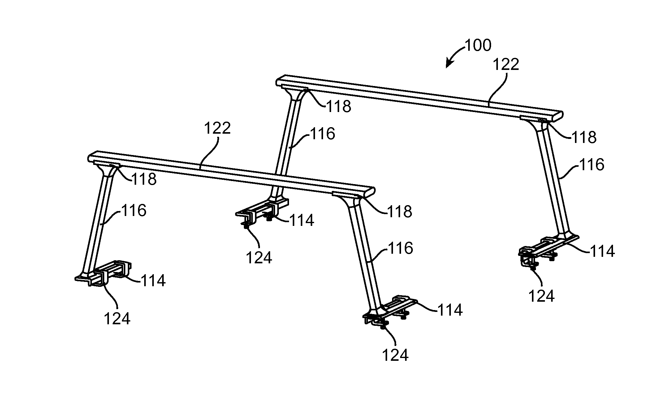
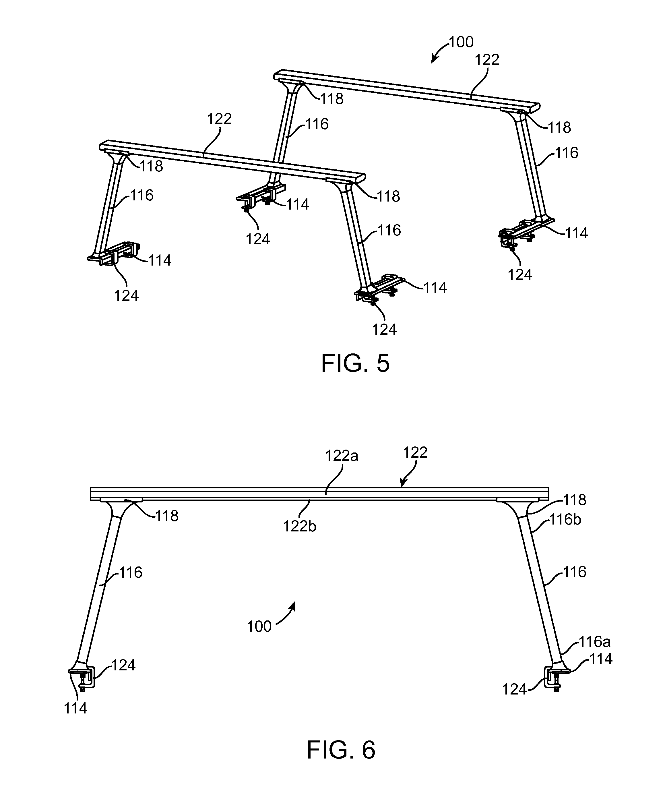
[0049]The modular rack system 100 of the present invention is shown in detail in FIGS. 5-28. Generally, FIGS. 5 and 6 show the overall new modular rack system 100 while FIGS. 8-10 show the structure of unique vertical upright tubular member 116 and FIGS. 11-18 show the horizontal base member 114 and its interconnection to the vertical upright tubular member 116. FIGS. 19-23 show the structure of the top saddle 118 in detail. FIGS. 24-28 show the interconnection of the top saddle 118 to the top rail 122 to complete the rack system 100 of the present invention. The top rail 122 is preferably of a length that can span across the distance between two side walls 20 of a vehicle. For example, the top rail 122 may be of a length of 65″ inches to 69.5″ inches, but can be any length to meet the given application at hand. FIG. 7 shows an exploded view of the three components of the horizontal base member 114, the vertical tubular member 116 and top saddle 118.

[0050]Referring first to FIGS. 5 ...


PUM


Abstract

A modular rack system, for adjustably attaching equipment to a vehicle, includes a base mountable on a side wall of the vehicle. The rack system has a first wall that is disposed on and upwardly emanating from the top surface of the base that defines a lower seat. One end of a vertical member resides in the lower seat and is secured thereto. The other end of the vertical member resides in an upper seat defining by a downwardly depending wall from a saddle and is secured thereto. The first and second walls laterally stabilize the vertical member relative to the base and saddle to permit the base to be mounted to a side wall of a vehicle and a top rail to be secured to the saddle without the use of gussets or cross-braces.

Description

CROSS REFERENCE TO RELATED APPLICATION[0001]This application is related to and claims priority from earlier filed provisional patent application Ser. No. 61 / 179,163, filed May 18, 2009, the entire contents thereof is incorporated herein by reference.BACKGROUND OF THE INVENTION[0002]This invention relates generally to equipment for vehicles, such as pickup trucks, and more particularly to a releasably attachable and adjustable rack system having sliding connections and many other accessories for attaching to the overhead rack of the vehicle.[0003]Vehicle racks and systems are very well known in the art. They can connect to various parts of the vehicle such as a cab and side walls of a truck bed. The rack systems that typically connect to a truck bed include a frame-like structure that includes a connection for attaching the rack to a vehicle as well as a structure for receiving accessories for customizing the rack system. For example, the rack system commonly includes a base or footi...

Claims


Application Information

Patent Timeline
Patent Type & Authority Applications(United States)
IPC IPC(8): B60R9/06
CPCB60R9/06B60R9/00B60R2021/0083B62D33/0207
Inventor MARR, JR., EDWIN L.
Owner THULE INC
Why Eureka
Try Eureka