Automotive exhaust component and method of manufacture

a technology for exhaust components and automobiles, applied in the direction of machines/engines, other domestic objects, separation processes, etc., can solve the problems of notoriously vulnerable loci of corrosive attack on welding, and achieve the effects of reducing diameter, high adaptability, and great flexibility

Inactive Publication Date: 2005-12-08
EVOLUTION IND INC
View PDF55 Cites 8 Cited by
  • Summary
  • Abstract
  • Description
  • Claims
  • Application Information

AI Technical Summary

Benefits of technology

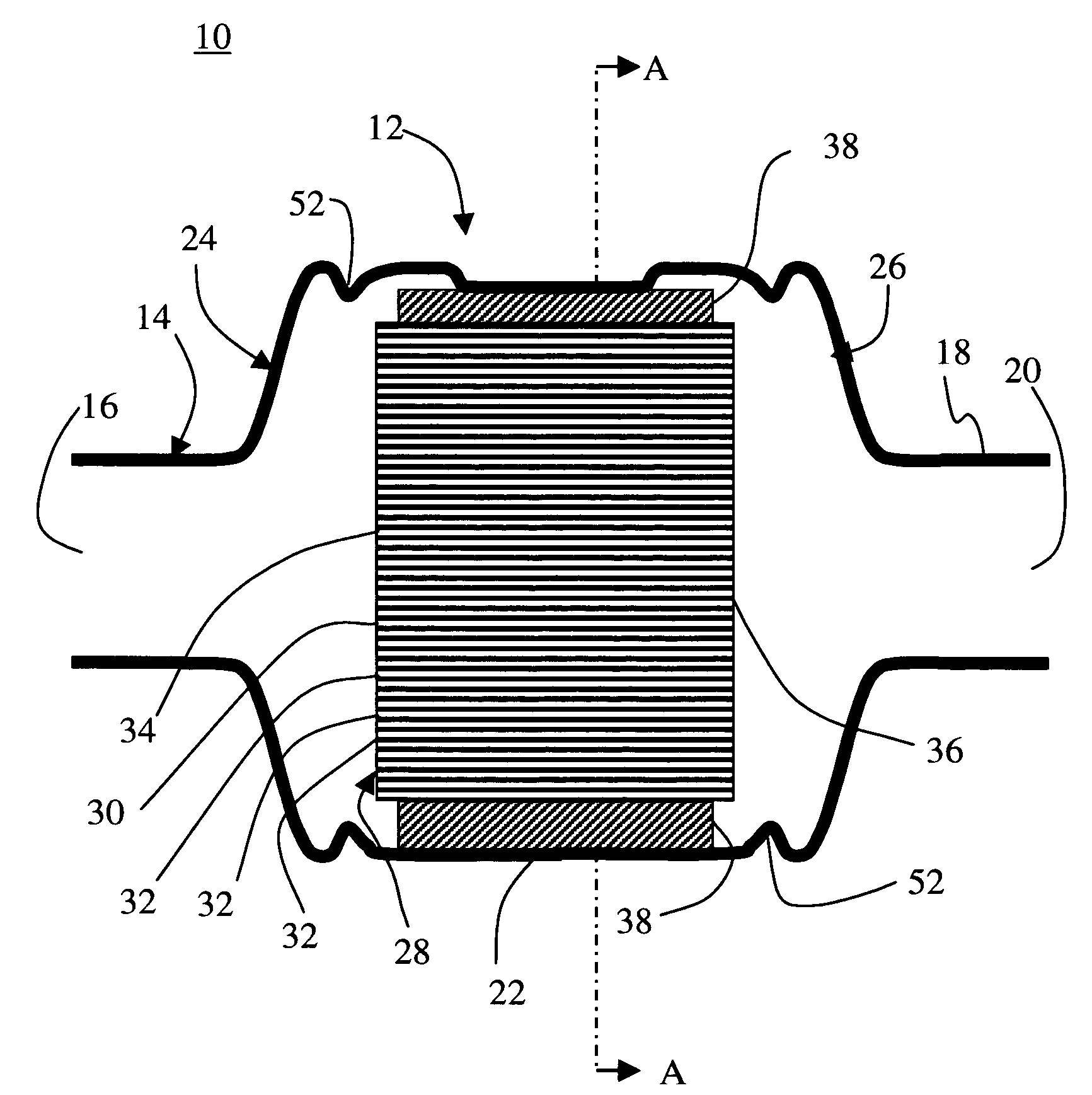
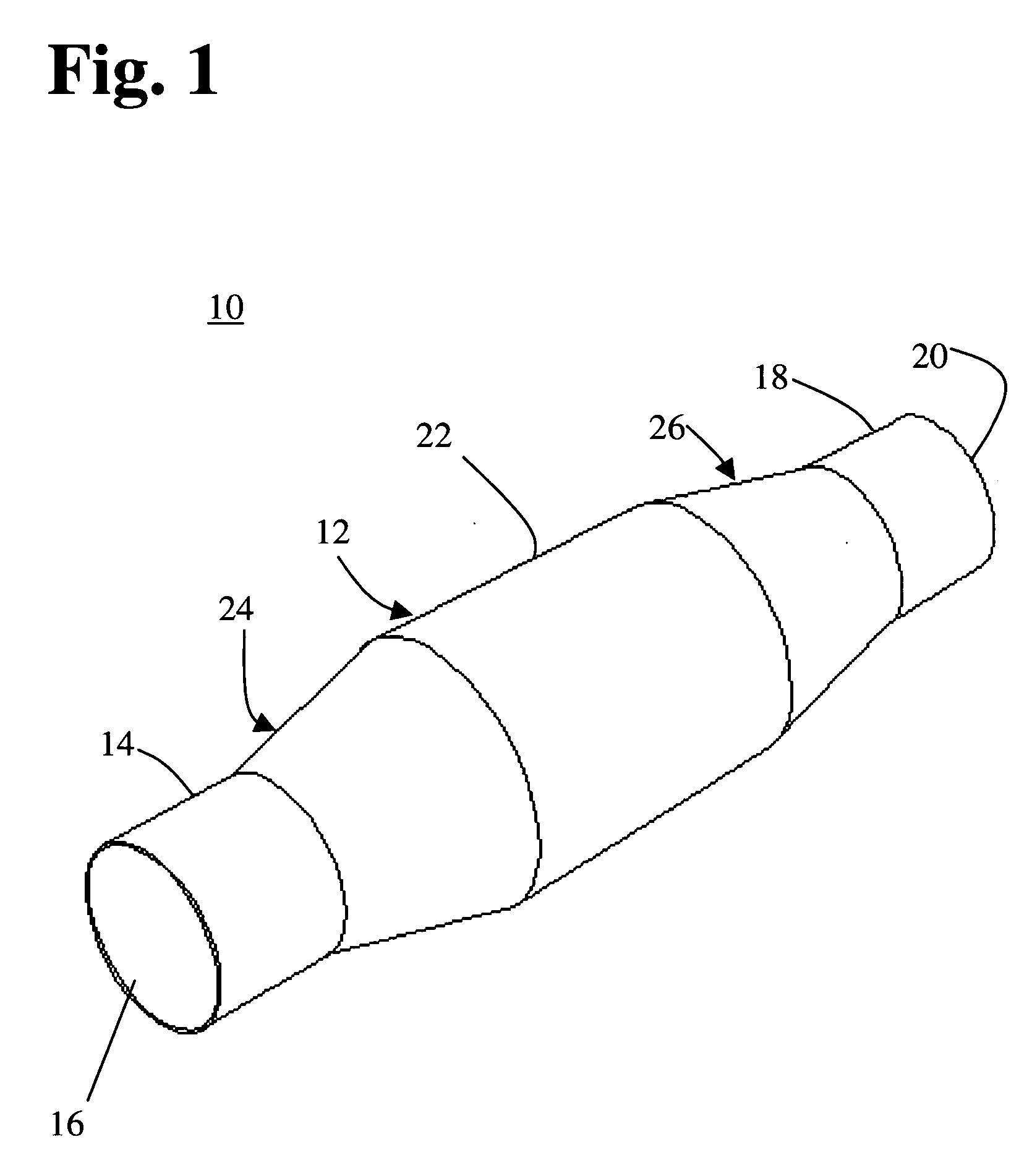
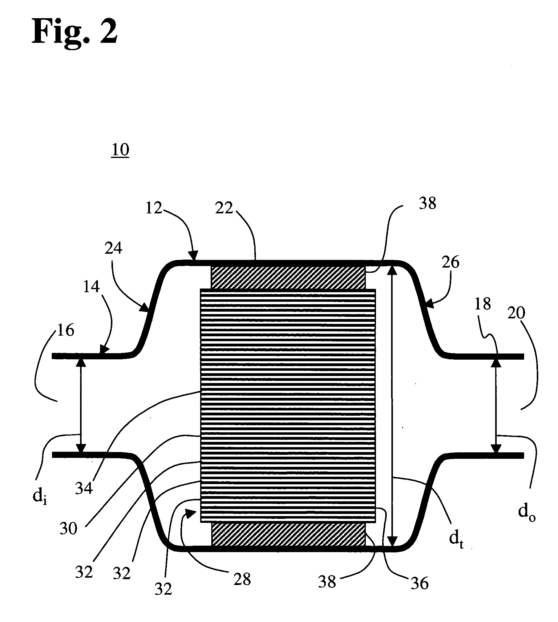
[0026] Compared to other known methods used to form ends, swaging affords a number of advantages. The reduction in diameter can be carried out in a sequence of steps using a plurality of dies. As a result, the swaging process is highly adaptable, providing a designer with great flexibility in tailoring a housing to fit into an available space and in optimizing the dynamics of gas flow through the device. The tubulated ends and transition sections are smooth and substantially free of circumferential ridges on either the inside or outside surfaces. The external appearance of the device is enhanced. The smoothness of the inside surface and the absence of ridges thereon minimizes generation of turbulence that impedes the flow of exhaust gas through the converter and causes excessive backpressure. Swaging maintains a level of ductility sufficient to allow the converter to be connected to the rest of the exhaust system by clamped, welded, or flanged joints.
[0027] A further advantage of the present method over spinning is its ability to form more intricate structures, including those having features such as extended length and bends or other non-symmetrical configuration. Since the present end-forming process does not entail rapid rotation of the workpiece, neither balance nor the size of available lathes or similar machine

Problems solved by technology

Welds are notoriously vulnerable as loci of corros

Method used


Image

  • Automotive exhaust component and method of manufacture
  • Automotive exhaust component and method of manufacture
  • Automotive exhaust component and method of manufacture

Examples


example 1

Preparation and Testing of a Catalytic Converter

[0058] A catalytic converter of a type commonly used for emissions reduction from an automobile engine was formed using a catalytic element comprising a conventional platinum-group noble metal type of catalyst supported on the walls of multiple passages extending through a cordierite ceramic honeycomb structure. The honeycomb structure was about 3.6 inches in diameter and 3 inches long. The housing for the converter was formed from a seamless tube of 409 stainless steel alloy having an outside diameter of about four inches and 0.049 inch walls. The honeycomb structure was wrapped with an intumescent mat compressed to about 0.12 inches thickness, and the combined mat and ceramic were then inserted into the center part of the generally tubular converter housing. The ends of the housing were then end-formed to provide an inlet port section and an outlet port section, each of which having a diameter of two inches and a length of two inche...


PUM


Abstract

A catalytic converter for an internal combustion engine exhaust system comprises a single-piece, seamless metal housing having tubulated gas inlet and outlet ports and a tubulated intermediate section with a catalytic element therein. The intermediate section is connected to the inlet port by an inlet transition section and to the outlet port by an outlet transition section. The inlet and outlet ports and the inlet and outlet transition sections are formed by swaging the ends of a seamless tube used to form the housing. Exhaust gas produced by operation of the engine passes into the converter and through the catalytic element. Noxious substances in the exhaust, including CO, NOx, and incompletely combusted hydrocarbons are converted to more benign substances through the action of the catalytic element, which is preferably a frangible ceramic honeycomb structure having a plurality of internal passages coated with a catalytically active substance. A swaging process is used to form tubulated ends on the converter. The tabulated ends minimize production of turbulence in the gas flow and allow the converter to be connected to the rest of the exhaust system by clamped, welded, or flanged joints. The one-piece, seamless construction of the converter is economical to produce and eliminates welding of housing components that tend to fail when subjected to corrosive exhaust gasses over a prolonged period of time.

Description

RELATED U.S. APPLICATION DATA [0001] This application is a divisional of co-pending U.S. patent application Ser. No. 10 / 389,868, filed Mar. 18, 2003, and further claims the benefit of U.S. Provisional Patent Application Ser. No. 60 / 367,419, filed Mar. 26, 2002. application Ser. Nos. 10 / 389,868 and 60 / 367,419 are incorporated herein in their entirety by reference thereto.BACKGROUND OF THE INVENTION [0002] 1. Field of the Invention [0003] This invention relates to the field of automotive exhaust components; and more particularly, to a muffler, catalytic converter or the like, that is formed and housed within a seamless enclosure. [0004] 2. Description of the Prior Art [0005] It is widely recognized that the exhaust emissions of internal combustion engines constitute a major source of air pollution throughout the world. The combustion process in these engines inevitably results in the production of certain substances that pass into the exhaust stream and are detrimental to the health a...

Claims


Application Information

Patent Timeline
IPC IPC(8): B01D53/94F01N3/28
CPCB01D53/9454F01N3/2853F01N3/2857Y02T10/22Y10T29/49345Y02T10/12
Inventor LANCASTER, PAUL B.TURSKY, JOHN M.
Owner EVOLUTION IND INC
Why Eureka
Try Eureka