Medical implant having a curlable matrix structure

a technology of curvature and matrix structure, applied in the field of medical implants, can solve the problems of stents that have to be expanded first, stents can easily be compressed, and risk of vessel injury, so as to facilitate handling and enhance the sliding

Inactive Publication Date: 2007-11-27
USSC MEDICAL GMBH
View PDF19 Cites 244 Cited by
  • Summary
  • Abstract
  • Description
  • Claims
  • Application Information

AI Technical Summary

Benefits of technology

[0011]An implant according to the present invention consists of a flat object that, as a result of its impressed and superimposed structure, assumes the form of a slotted tube or hose with the free edges preferably overlapping. In its volume-reduced form it continues to be present in a curled-up condition, i.e., the diameter of the implant, in a volume-reduced state, is significantly reduced in comparison to that of the superimposed structure. After the implant has been released, it assumes the structure impressed on it and expands to such an extent that the vessel surrounding the implant allows. Such an expansion in the form of an expanding spiral spring shape leads to the implant automatically adapting to the vessel caliber or lumen in such a manner that it can be applied in vessels having different calibers. In the case of narrow vessels, this results in a relatively wide overlap of the two free edges, with wider vessels this overlap is smaller or even a free gap forms which, in the event of vessel branches, is a desirable trait.
[0022]As per one embodiment, the system has additionally been provided with a second micro-catheter to accommodate the second guide wire with the implant in such a way that it is slidable within the second micro-catheter and can be moved through the first micro-catheter to the target site. Coatings of the second micro-catheter that enhance its slidability may facilitate handling.

Problems solved by technology

It is, however, problematic that on account of their plastic deformability these stents can easily be compressed when external pressure is exerted on them.
Another disadvantage is encountered when anchoring such a stent, by applying high pressure, the stent has to be expanded initially beyond the circumferential size it will finally have.
Such an expansion beyond the required circumferential size may involve the risk of a vessel injury that may entail the formation of a thrombus.
Further, these traditional balloon-dilatable stents, due to their structure, cannot simply be introduced through an already laid micro-catheter and advanced to the implantation site but have to be arranged in the distal area of a specially designed micro-catheter in order to be moved to the implantation location by means of a so-called pusher.
This process calls for a rather sophisticated catheter technology that is difficult to handle.
Additionally, a stent, once placed in position, can only be relocated or retrieved with great difficulty, if at all.
Such stents, as well, require mechanisms for their introduction that are relatively expensive and space-consuming.
The known super-elastic expandable stent requires the use of a supporting and guiding sheath that results in a relatively large catheter size and, what is more, also makes it difficult to introduce such stents through an already laid catheter.

Method used


Image

  • Medical implant having a curlable matrix structure
  • Medical implant having a curlable matrix structure
  • Medical implant having a curlable matrix structure

Examples


Embodiment Construction

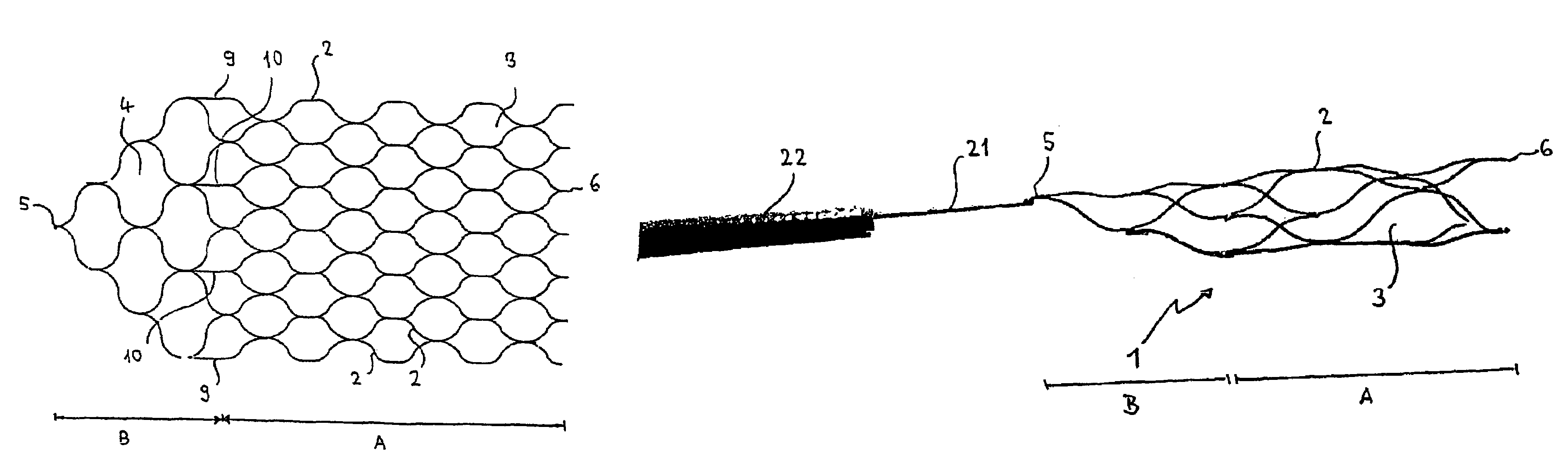
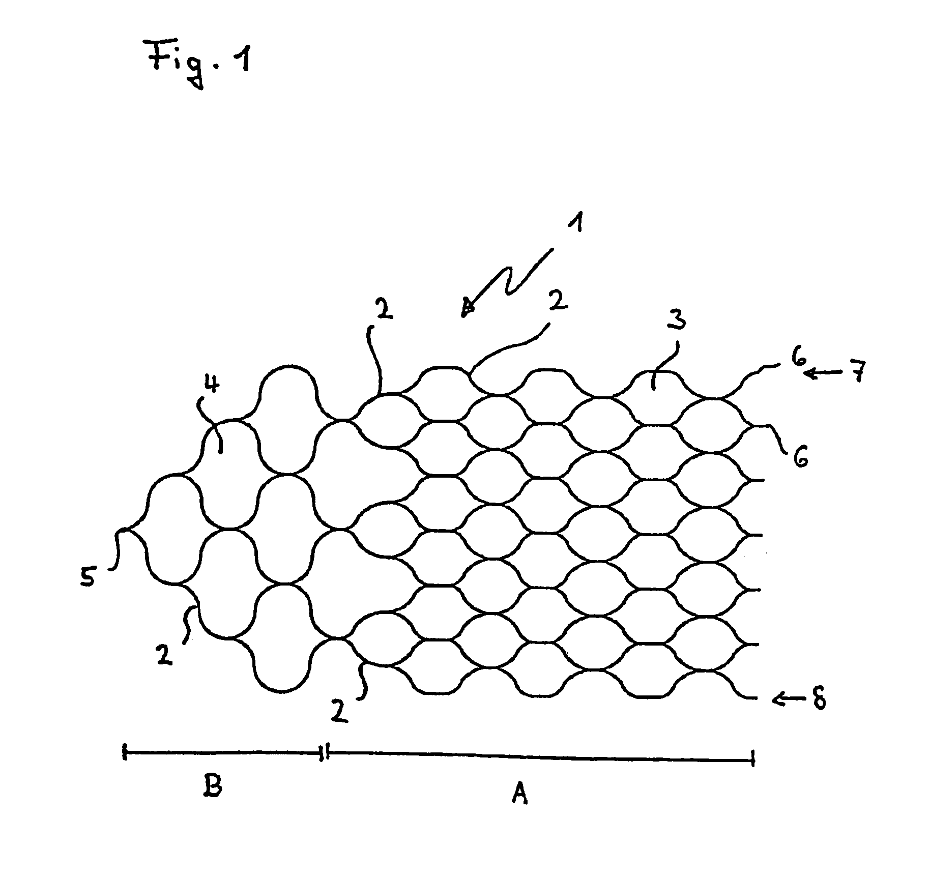
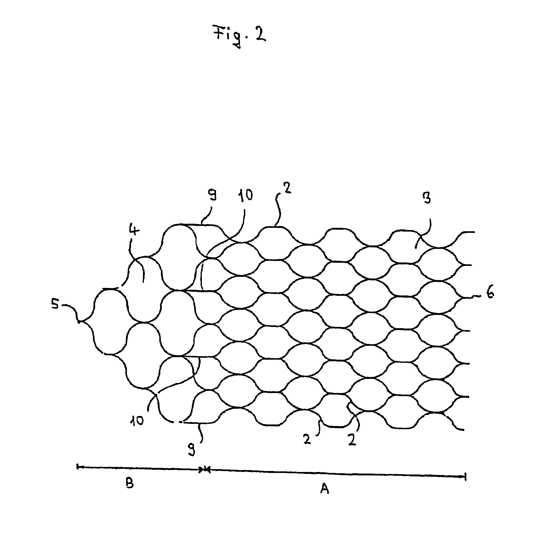
[0032]An implant, according to FIG. 1, consists of a mesh or honeycomb structure that, in one embodiment, comprises a multitude of filaments interconnected by a laser welding technique. The implant can be subdivided into a functional structure A and a tapering proximal structure B, the two structures being distinguishable, inter alia, by a different mesh size. To enable the functional structure A to perform its retaining function, its mesh cells 3 are held relatively narrow so that they lend themselves to the retention of occlusion spirals arranged in an aneurysm. In general, the mesh width is in the range of 0.5 to 4 mm and may vary within an implant.

[0033]In one aspect of the present invention, the implant is a flat or two-dimensional structure that is rolled up to form a longitudinally open object capable of establishing close contact with the wall of the vessel into which it is introduced.

[0034]In the tapering proximal structure B of the implant, there is provided a wider mesh c...


PUM


Abstract

A medical implant, having a proximal and a distal end, that is preformed to assume a superimposed structure at an implantation site but can be made to take on a volume-reduced form making it possible to introduce it with a micro-catheter and a guide wire arranged at the proximal end, with the implant in its superimposed structure assuming the form of a longitudinally open tube and having a mesh structure of interconnected strings or filaments. The implant has a tapering structure at its proximal end where the strings or filaments converge at a connection point.

Description

RELATED APPLICATIONS[0001]This is a continuation application of PCT International Application No. PCT / EP2003 / 007926 filed Jul. 21, 2003 which claimed priority of German Patent Application No. 102 33 085.9 filed Jul. 19, 2002, the contents of all of which are incorporated herein by reference.FIELD OF THE INVENTION[0002]The present invention relates to a medical implant that is preformed in order to assume, at the site of implantation, a superimposed structure and while being implanted is presented in a volume-reduced form. Furthermore, the present invention relates to the application of such an implant as a neuro-stent, its combination with a guide wire as well as a system for the application of such implants when treating aneurysms or other vascular malformations.BACKGROUND OF THE INVENTION[0003]It is known to treat vascoconstriction (stenoses) with stents (vascular endoprostheses, vessel props) that are inserted into the stenotic area to keep the vessel lumen open. It is further kn...

Claims


Application Information

Patent Timeline
Patent Type & Authority Patents(United States)
IPC IPC(8): A61F2/88A61F2/84A61F2/92A61B17/00A61B17/12A61F2/00A61F2/90A61F2/91A61F2/915A61F2/95A61M25/01
CPCA61B17/12118A61F2/966A61F2/91A61F2/915A61F2/92A61F2/95A61F2/82A61B17/221A61B2017/12063A61B2017/2215A61F2002/3008A61F2002/91525A61F2002/91541A61F2002/91558A61F2250/0098A61F2220/005A61F2220/0058A61F2230/0008A61F2002/9528A61F2002/9534
Inventor HENKES, HANSFLESSER, ACHIMKONTEK, RONALDSPEDER, JURGENBODENBURG, RALPH
Owner USSC MEDICAL GMBH
Why Eureka
Try Eureka