Vascular Stents, Methods of Use and Methods of Manufacture

Inactive Publication Date: 2009-08-06
BOUDJEMLINE YOUNES
View PDF8 Cites 243 Cited by
  • Summary
  • Abstract
  • Description
  • Claims
  • Application Information

AI Technical Summary

Benefits of technology

[0021]Preferably, interlacing a strand with other encountered strands is performed as a braiding process, i.e. this strand runs alternately on a strand on its way then under the following strand, and so on. This braiding allows the structure to be used as a stent or to serve as a blank for the production of other implants (e.g., plugs). The braiding also enables a reliable stop of the first and of the last strands formed by the wire.
[0022]The wire used may be a shape memory alloy, in particular a nickel-titanium alloy, known under the designation “NITINOL”, having a diameter ranging from, for example, 0.15 to 0.5 mm. The diameter of the structures which may be produced by the method according to the invention very widely, and may range from 5 to 100 mm (for example). The method may include the step of placing on the structure a means for longitudinal shortening of the structure—that is, the ability to switch from an elongated state to a shortened state. Longitudinal shortening may also enable the deployment of the structure or facilitate the deployment of the structure. The means for accomplishing longitudinal shortening may include an elastic means—for instance, a band made of elastic material, notably of si

Problems solved by technology

The shortcoming of these stents and plugs lies in their being relatively difficult to produce.
One of the shortcoming of known stents is their lack of adaptability with regard to variations in diameter of vessels in which they are used.
Moreover, current stents include ends which are relatively aggressive wh

Method used


Image

  • Vascular Stents, Methods of Use and Methods of Manufacture
  • Vascular Stents, Methods of Use and Methods of Manufacture
  • Vascular Stents, Methods of Use and Methods of Manufacture

Examples


Embodiment Construction

[0077]This application claims priority to EP application no. 06290707.6 of the same title, which is a continuation-in-part to U.S. patent application Ser. No. 10 / 514,329, filed Jul. 6, 2005, which is a national stage application of PCT application no. PCT / FR03 / 03296, filed Nov. 5, 2003, which claims priority to French application no. FR 02 14522, filed Nov. 20, 2002. Each of the foregoing disclosures is herein incorporated by reference.

[0078]While some of the embodiments of the present invention are described herein as being manufactured according to the structures illustrated in FIGS. 1-8, and corresponding methods described herein, some embodiments of the present invention may also be manufactured using laser micromaching / cutting.

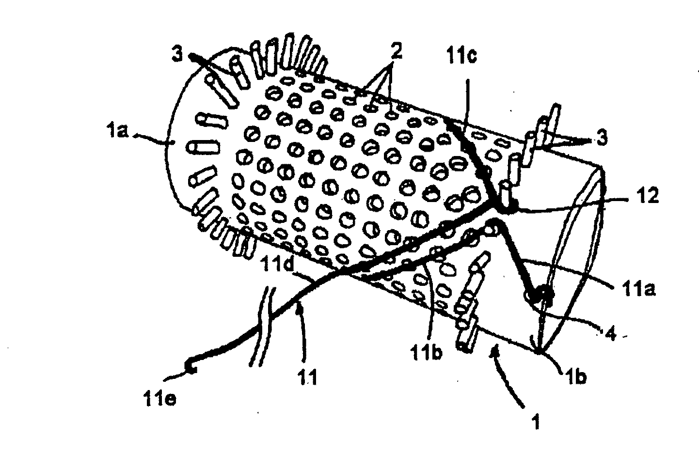
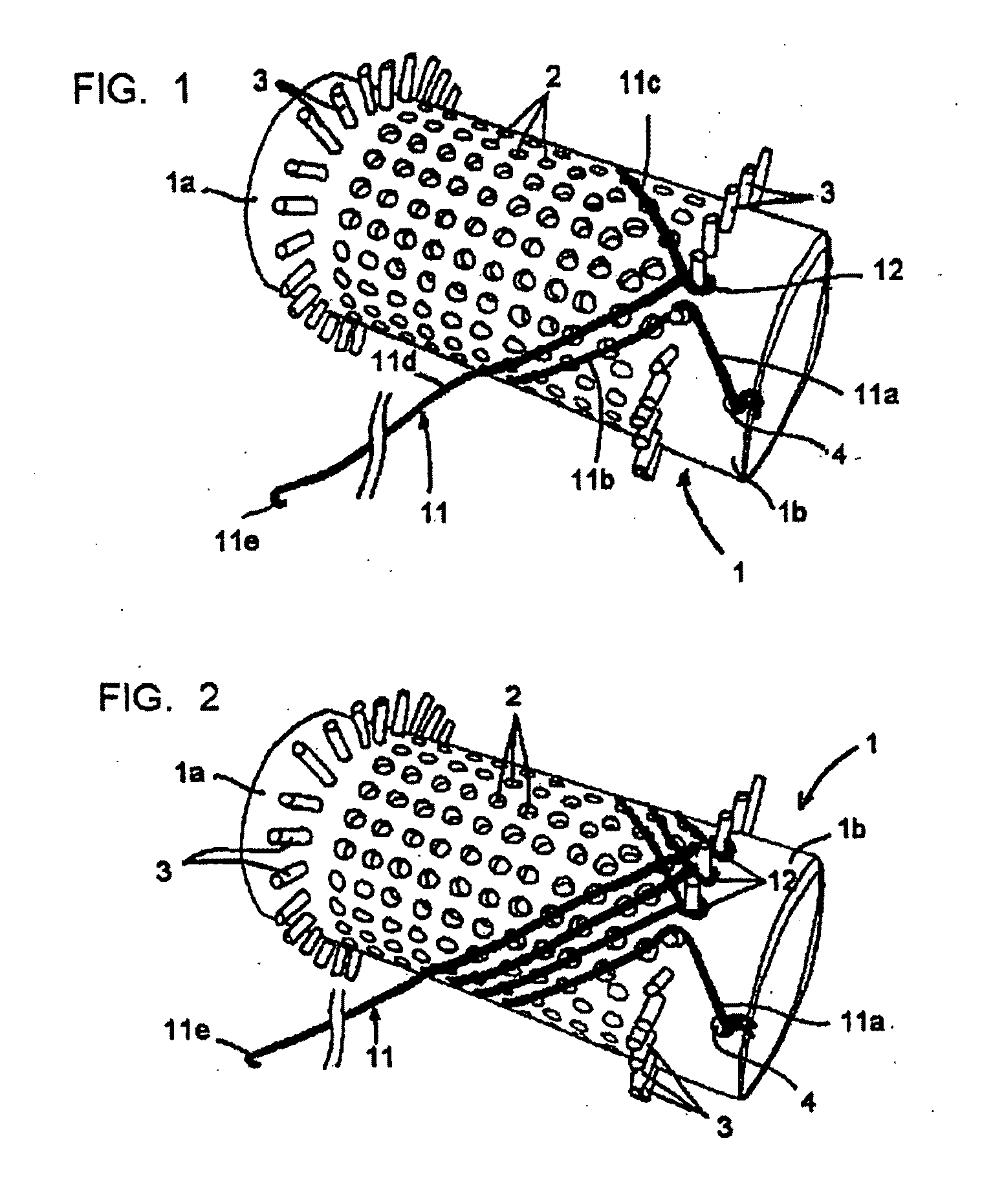
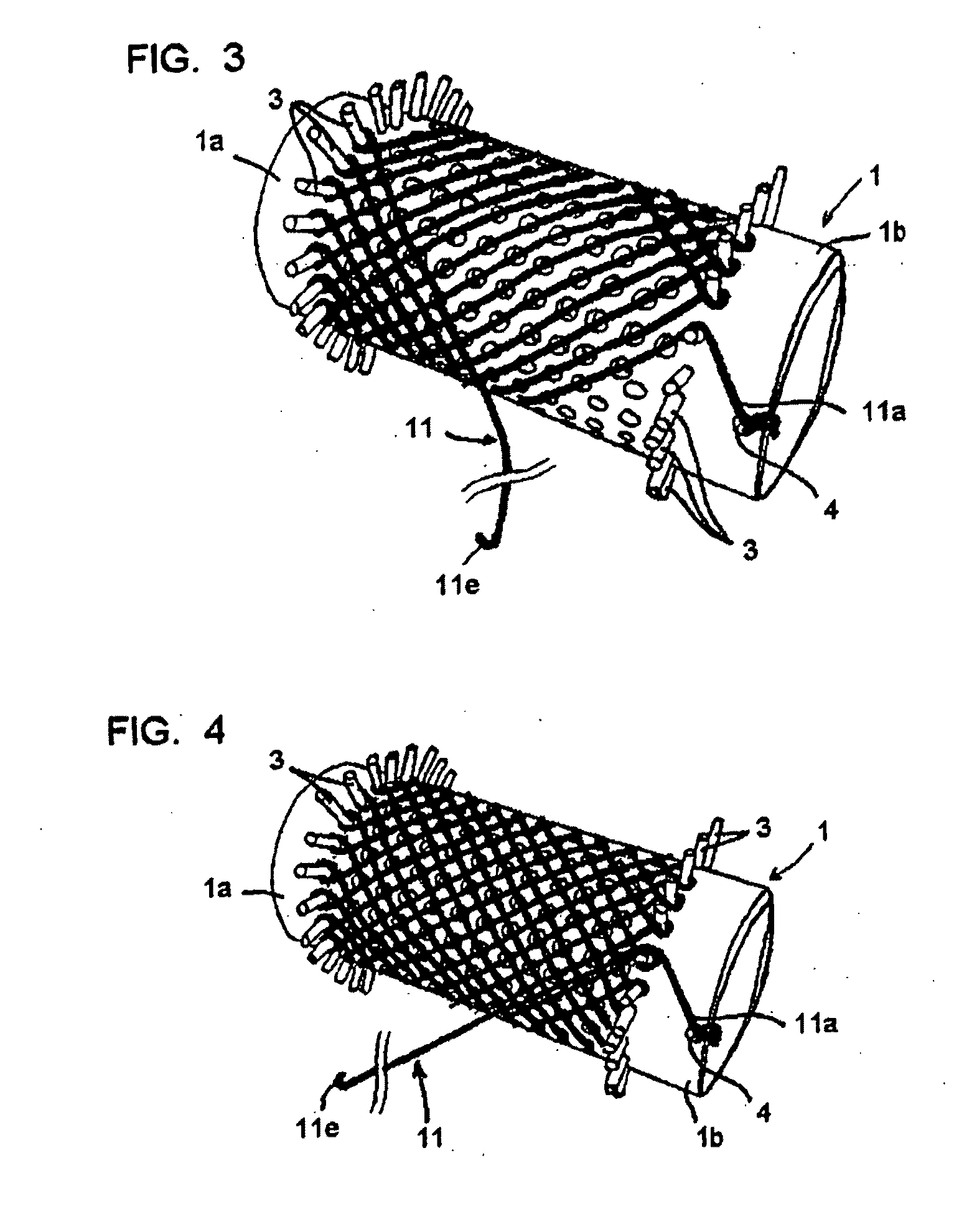
[0079]For simplification purposes, the portions or element present on the different devices and structures will be designated by the same numeric references and will not be described again. FIG. 1 represents a tubular chuck 1 drilled with holes 2 evenly d...


PUM


Abstract

Embodiments of the present invention are directed to medical implants/stents, systems, and methods of treatment using such stents. Some embodiments of the invention include a self-expanding stent having a tubular first wall structure of a first diameter, where each end portion of the first wall structure is formed into a second wall structure of a second diameter larger than the first diameter. A membrane covers at least the first wall structure and the stent includes an interlaced, helicoidally wound wire forming a mesh-like structure.

Description

FIELD OF THE INVENTION[0001]Embodiments of the present invention are directed generally to stent devices, and more particularly, to stents for vascular applications, including diametrical reduction and valve replacement in vascular applications. Some of the embodiments of the present invention are also directed to applications and methods of use for such stents, as well as methods of manufacture for such stents.BACKGROUND OF THE INVENTION[0002]It is well-known that a section of the lumen of a corporeal duct may be restored by means of a tubular extension. Such an extension, which may be referred to as a “stent”, is deformable between a contracted state and a deployed state. In a contracted state, the stent is capable of introduction and movement along a corporeal duct up to the site to be treated, while the deployed state enables the stent to rest against the wall of the conduit at the site to be treated and restores the section of the conduit. Such a stent may also be used for impl...

Claims


Application Information

Patent Timeline
IPC IPC(8): A61F2/06A61F2/07A61F2/82A61F2/852A61F2/90
CPCA61F2/07D10B2509/06A61F2/852A61F2/90A61F2002/072A61F2002/826A61F2250/0007A61F2250/0039A61F2250/0048A61F2250/0063A61F2250/0098D04C1/06D04C3/48D04C7/00A61F2220/0075A61F2230/0065A61F2230/0076A61F2230/0078A61F2230/008A61F2/2418
Inventor BOUDJEMLINE, YOUNES
Owner BOUDJEMLINE YOUNES
Why Eureka
Try Eureka