Electronic circuitry

Inactive Publication Date: 2003-01-09
ANALOG DEVICES INC
View PDF0 Cites 40 Cited by
  • Summary
  • Abstract
  • Description
  • Claims
  • Application Information

AI Technical Summary

Benefits of technology

0008] One broad view or aspect of this invention resides in the concept and realisation of method and means for effectively integrating or synergistically combining distribution of repeating pulse or cyclic signals with active means for producing and maintaining those signals. A composite electromagnetic/semicondu

Problems solved by technology

Nowadays, at much higher operating frequencies, typically aiming for 300 MHz to 1 GHz, inherent on-chip distribution problems associated with clock signal reflection and skew have become highly significant as binary signal widths/durations are no longer so much shorter than clock signal pulses.
Clock signal generation is presently typically by frequency multiplication from off-chip crystal clock oscillators using on-chip phase locked loop (PLL) control circuitry which occupies valuable chip area, consumes considerable power, and experiences problems with signal

Method used


Image

  • Electronic circuitry
  • Electronic circuitry
  • Electronic circuitry

Examples


Example

[0060] Known transmission-lines broadly fall into two categories in that they are either open-ended or specifically terminated either partially or fully. Transmission-lines as proposed herein are different in being neither terminated nor open-ended. They are not even unterminated as such term might be understood hitherto; and, as unterminated herein, are seen as constituting a structural aspect of invention, including by reason of affording a signal path exhibiting endless electromagnetic continuity.

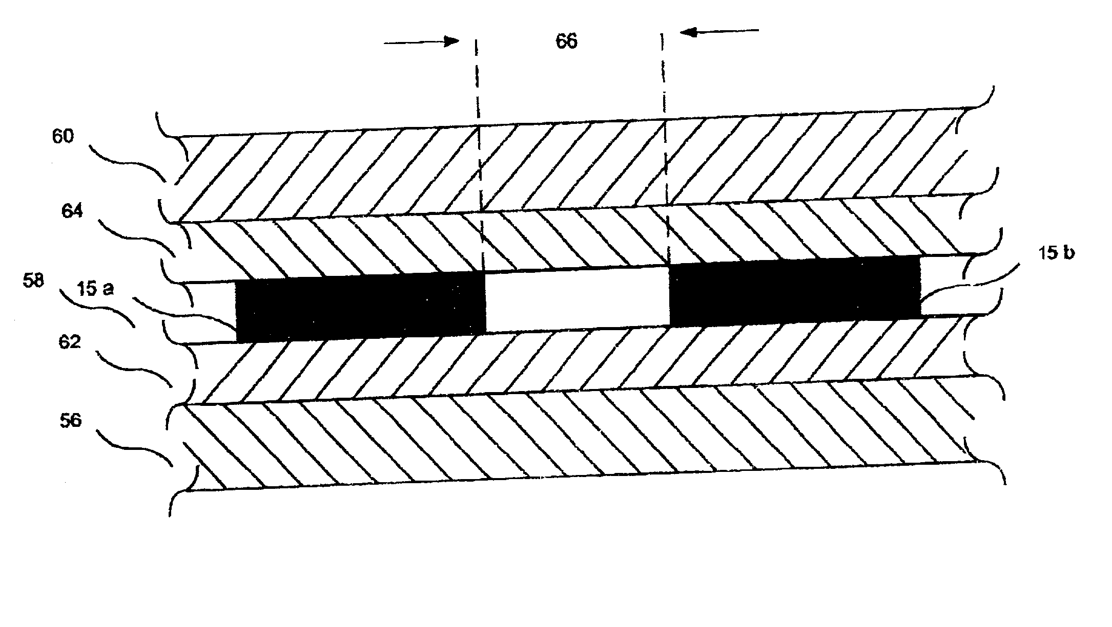
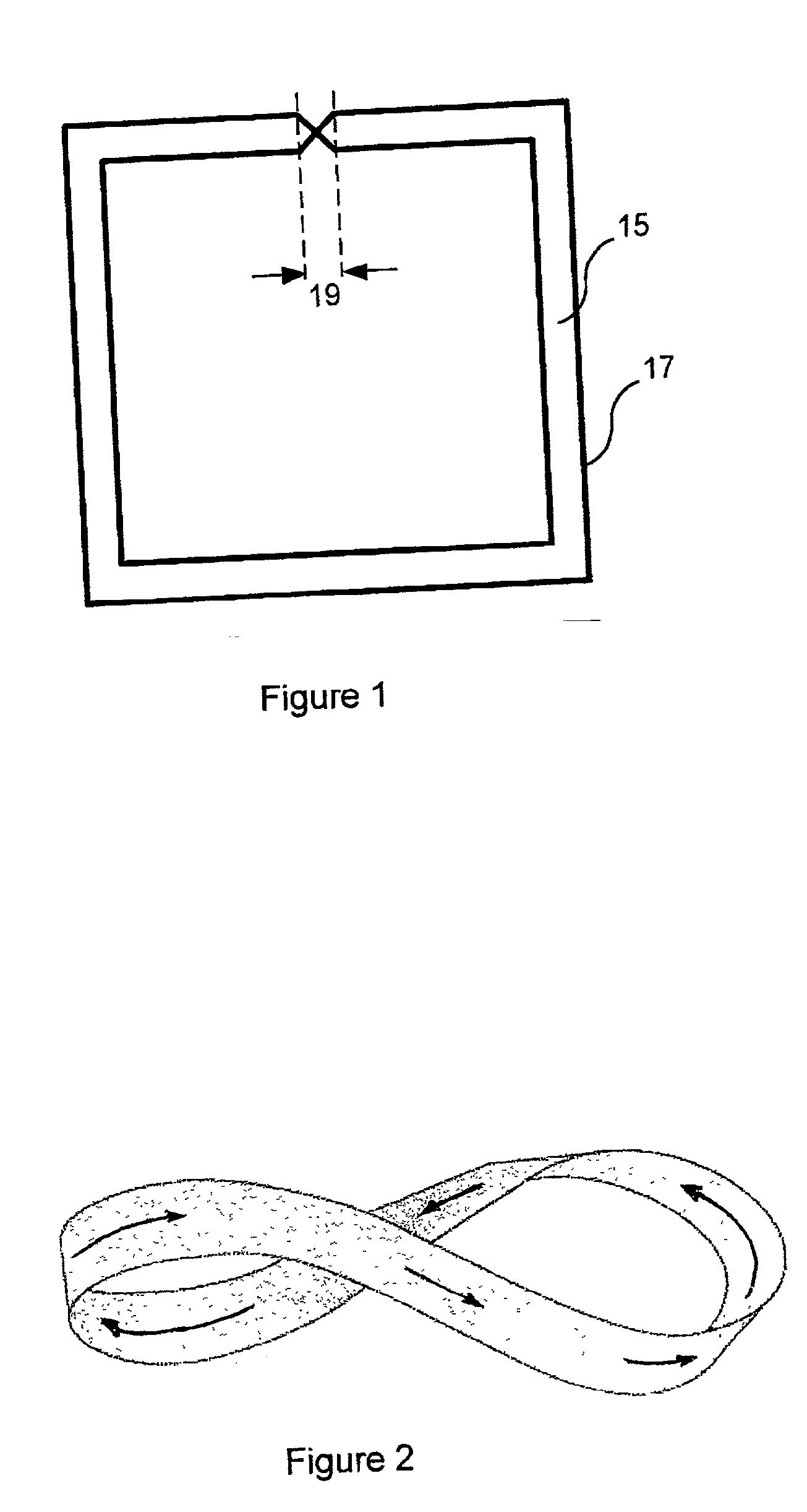
[0061] FIG. 1 shows such a transmission-line 15 as a structure that is further seen as physically endless, specifically comprising a single continuous "originating" conductor formation 17 shown forming two appropriately spaced generally parallel traces as loops 15a, 15b with a cross-over at 19 that does not involve any local electrical connection of the conductor 17. Herein, the length of the originating conductor 17 is taken as S, and corresponds to two `laps` of the transmission-line 1...


PUM


Abstract

Timing signal generation and distribution are combined in operation of a signal path exhibiting endless electromagnetic continuity affording signal phase inversion and having associated regenerative active means. Two-or more-phases of substantially square-wave bipolar signals arise directly in travelling wave transmission-line embodiments compatible with semiconductor fabrication including CMOS. Coordination by attainable frequency synchronism with phase coherence for several such oscillating signal paths has intra-IC inter-IC and printed circuit board impact, as does two-way simultaneous data transfer.

Description

[0001] The invention relates to electronic circuitry concerning timing signals and their production and distribution; oscillators as sources of such as timing signals; and communications according to timing signals.BACKGROUND TO INVENTION[0002] Digital electronic data processing circuitry and systems require timing signals to synchronise data processing activities. Customarily, such timing signals include a master timing signal from which other timing signals can be derived. Such a master timing signal is commonly referred to as a `clock` signal. It is often desirable to have a clock signal that is available in more than one phase.[0003] An example of a two-phase clock signal is where available clock signals have a phase difference of 180-degrees as often used for dynamic logic and shift register circuitry. An example of a four-phase clock signal is where available clock signals have successive phase differences of 90-degrees. Semiconductor integrated circuits (ICs or chips) are typ...

Claims


Application Information

Patent Timeline
IPC IPC(8): G06F1/10H03K3/03H03K3/86H03K5/00
CPCG06F1/10H03K3/03H03K3/86H03L7/00H03B5/1852
Inventor WOOD, JOHN
Owner ANALOG DEVICES INC
Why Eureka
Try Eureka