Percutaneous annuloplasty system with anterior-posterior adjustment

a technology of annuloplasty and anterior-posterior adjustment, which is applied in the field of treating and repairing heart valves, can solve the problems of preventing the valve from sealing properly, long recovery time, and high risk of infection in patients, and achieves the effects of reducing the a-p diameter reducing the a-p distance of the annuloplasty ring, and improving the coaptation of the leaflets of the heart valv

Active Publication Date: 2013-08-29
VALCARE INC
View PDF8 Cites 247 Cited by
  • Summary
  • Abstract
  • Description
  • Claims
  • Application Information

AI Technical Summary

Benefits of technology

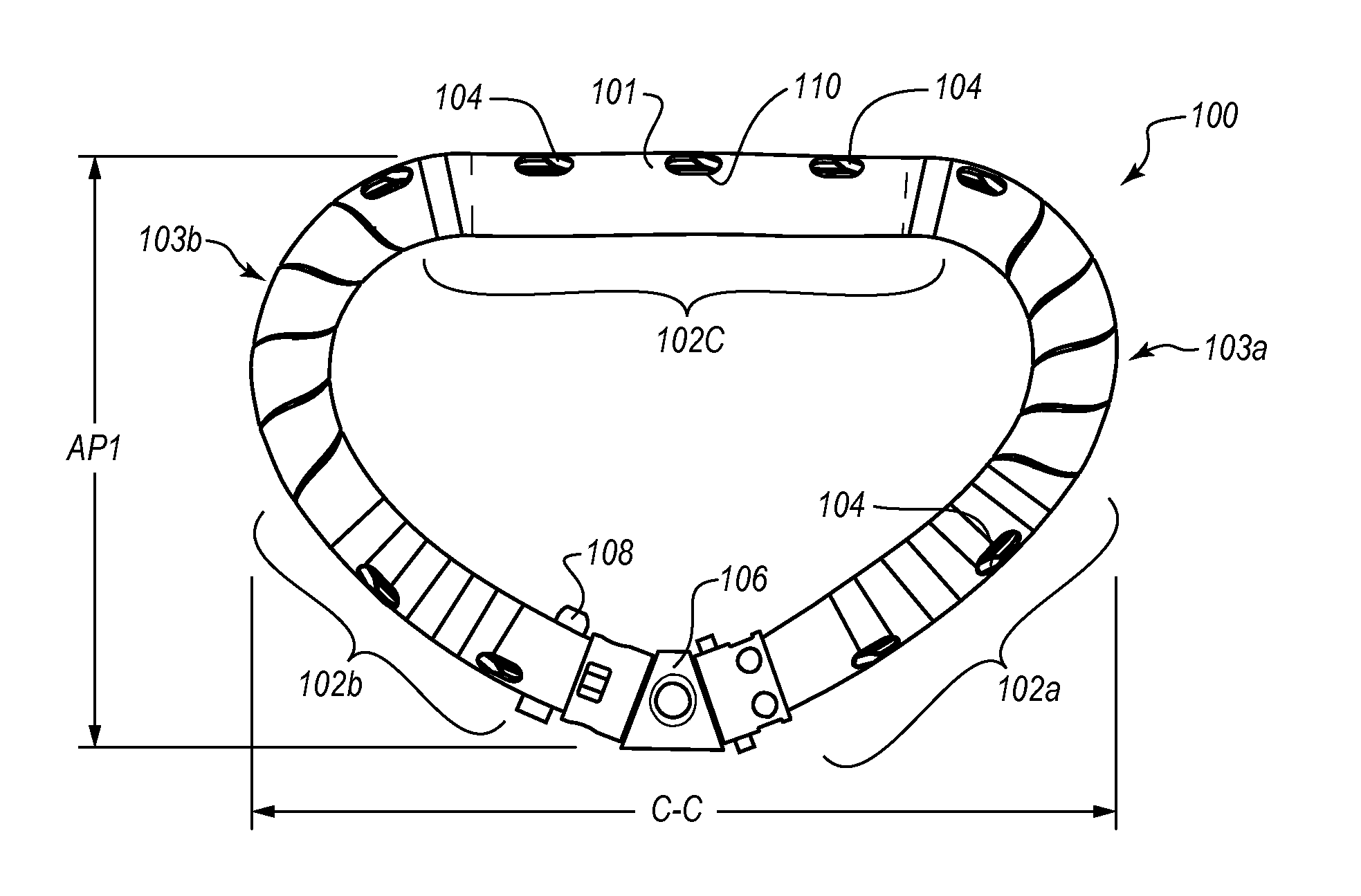
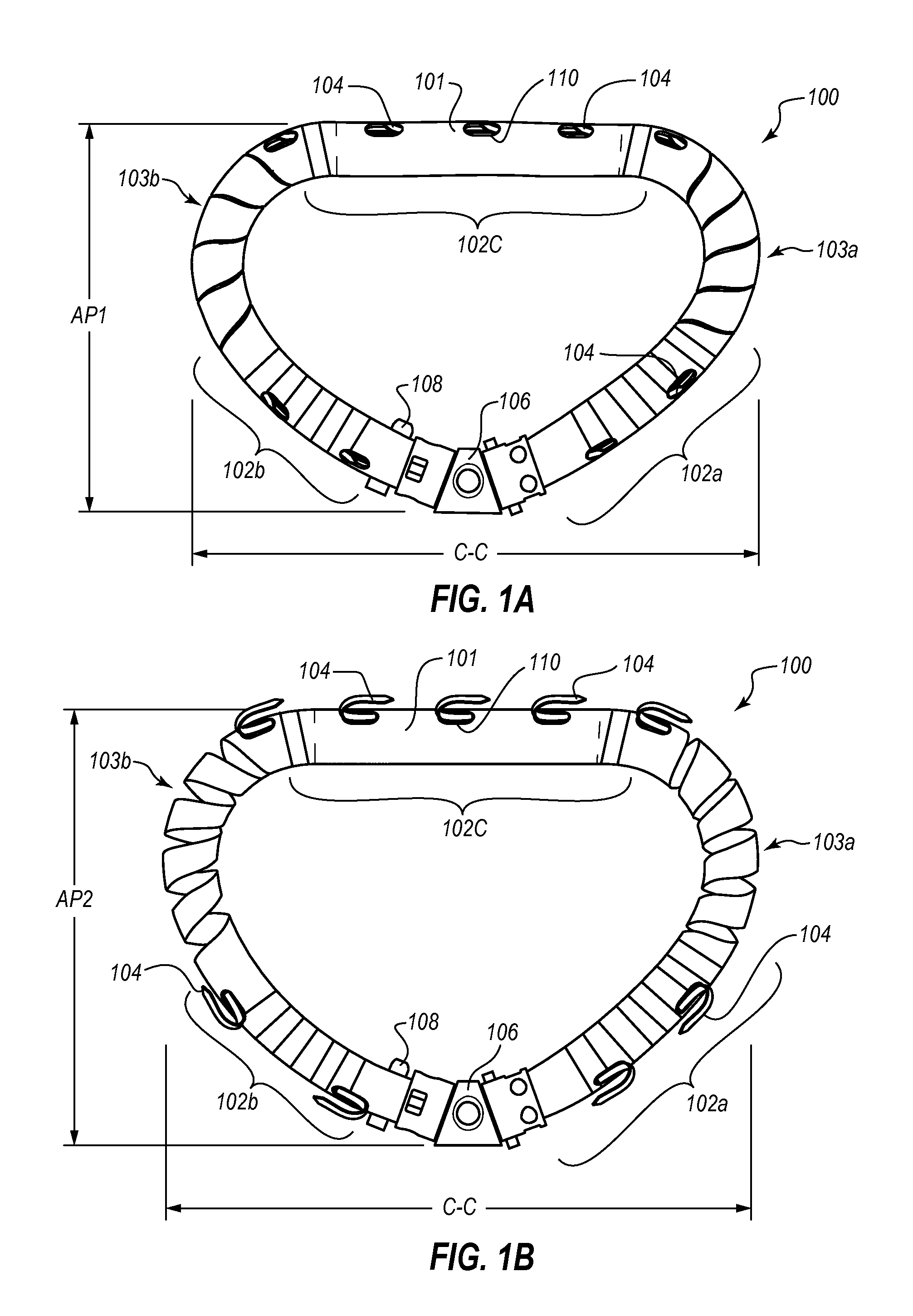
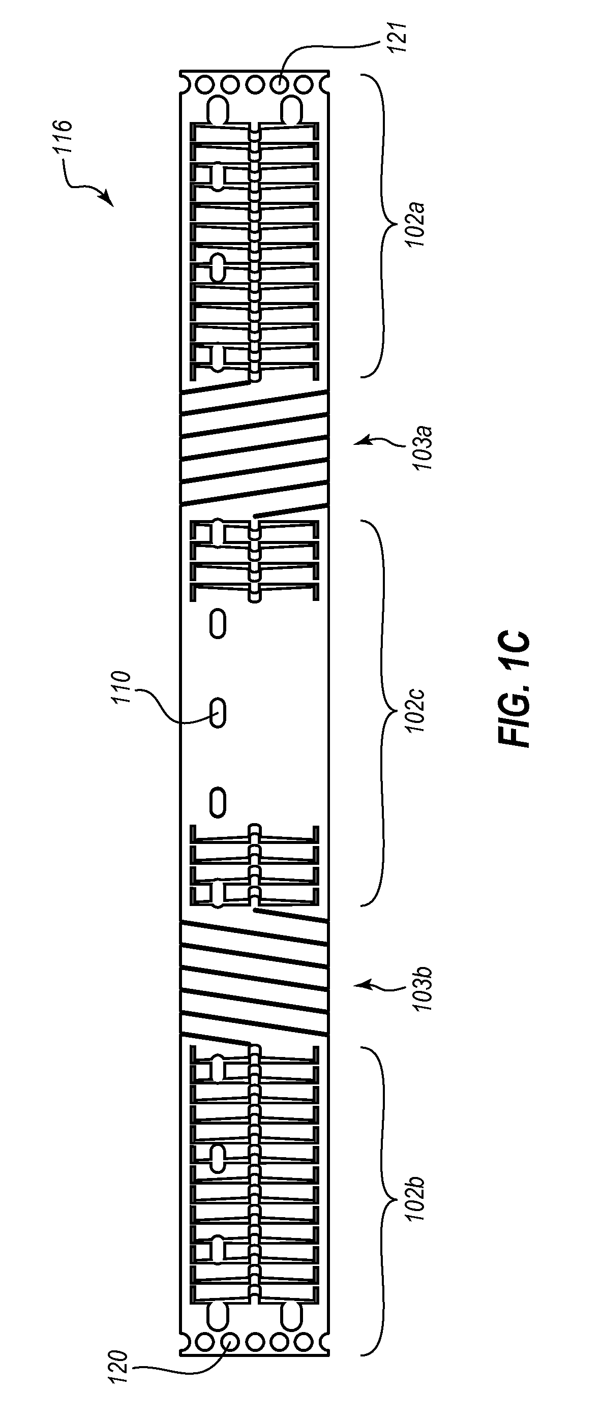
[0006]In one embodiment, an annuloplasty ring includes an outer hollow body member including a plurality of regions or segments. Adjacent regions or segments cooperate with one another to enable the body member to transition from an elongate insertion geometry to an annular operable geometry. The annuloplasty ring in the annular operable geometry can be expanded by an expansion tool to increase an anterior-posterior (A-P) diameter of the annuloplasty ring to an expanded state in intimate contact with tissue of a heart valve annulus. The annuloplasty ring also includes an internal anchor member located at least partially within the outer hollow member. The internal anchor member includes a plurality of anchors configured to fasten the annuloplasty ring to tissue of the heart valve annulus. The internal anchor member is configured to move the plurality of anchors with respect to a plurality of windows or gaps in the outer hollow body member to selectively deploy the plurality of anchors through the corresponding windows. The annuloplasty ring can be contracted from the expanded state to a contracted state to decrease the A-P diameter of the annuloplasty ring and decrease the A-P distance of the heart valve annulus to improve leaflet coaptation of the heart valve leaflets and reduce regurgitation through the heart valve.

Problems solved by technology

This causes the valve opening to enlarge, which prevents the valve from sealing properly.
The procedure can expose the patient to a high risk of infection and may result in a long and difficult recovery.
The recovery can be particularly difficult for patients in less than optimal health due to the effects of suffering from a heart valve defect such as regurgitation.

Method used


Image

  • Percutaneous annuloplasty system with anterior-posterior adjustment
  • Percutaneous annuloplasty system with anterior-posterior adjustment
  • Percutaneous annuloplasty system with anterior-posterior adjustment

Examples


example deployment

[0097 Approaches

[0098]As discussed above, the annuloplasty ring embodiments disclosed herein are configured for percutaneous transcatheter delivery and fixation to heart valves. The annuloplasty rings may be delivered through a catheter to the mitral valve, for example, using a trans-septal approach, a retrograde approach, or a trans-apical approach. For example, FIG. 8A is a schematic diagram illustrating a trans-septal approach for endovascular delivery of an annuloplasty ring (not shown) to the mitral valve 810 of a heart 800 according to one embodiment. For illustrative purposes, a partial cross-section of the heart 800 is illustrated to show the right atrium RA, right ventricle RV, left atrium LA, and left ventricle LV. For clarity, certain features (e.g., papillary muscles and chordae tendineae) are not shown. In the trans-septal approach shown in FIG. 8A, the left atrium LA is approached by advancement of a catheter 812 through the inferior vena cava 814, into the right atriu...

example expansion

[0108 Tool Embodiments

[0109]FIG. 10 is a schematic diagram illustrating a perspective, partial cross-sectional view of a heart 1000 during the expansion of an adjustable annuloplasty ring 1002 using a balloon tool 1004 as an expansion tool 1004, preparatory to affixation to the annulus of the mitral valve 1006 according to one embodiment. As shown, a delivery catheter 1010 extends from the left ventricle into the left atrium through the leaflets of the mitral valve 1006. Thus, this illustrated embodiment may correspond to, for example, a trans-apical approach or a retrograde approach, as discussed above. Artisans will recognize from the disclosure herein, however, that similar principles as those illustrated may be used for trans-septal approaches.

[0110]In FIG. 10, an expansion tool 1004 is being used to expand the annuloplasty ring 1002. The annuloplasty ring 1002 is positioned on or next to the annulus of the mitral valve 1006. The expansion tool 1004 is disposed within the annulo...


PUM


Abstract

Apparatus, systems, and methods are provided for repairing heart valves through percutaneous transcatheter delivery and fixation of annuloplasty rings to heart valves. An annuloplasty ring includes an outer hollow body member including a plurality of regions. Adjacent regions cooperate with one another to change the body member from an elongate insertion geometry to an annular operable geometry. Adjacent regions are coupled by a biasing element or a stepped connector to allow expansion to an expanded state and contraction to a contracted state in the annular operable geometry. The annuloplasty ring also includes an internal anchor member located at least partially within the body member and having a plurality of anchors configured to attach the annuloplasty ring to tissue of a heart valve annulus. An angled ring closure lock allows coupling of the ends of an annuloplasty ring at an apex of a D-shape annular operable geometry.

Description

RELATED APPLICATIONS[0001]This application claims the benefit under 35 U.S.C. §119(e) of U.S. Provisional Patent Application No. 61 / 604,856, filed Feb. 29, 2012, and titled “PERCUTANEOUS ANNULOPLASTY SYSTEM WITH ANTERIOR POSTERIOR ADJUSTMENT,” and of U.S. Provisional Patent Application No. 61 / 734,904, filed Dec. 7, 2012, and titled “ROTATIONAL BARBS,” each of which is hereby incorporated herein by reference in its entirety.TECHNICAL FIELD[0002]The present disclosure relates to treating and repairing heart valves, and specifically to apparatus, systems, and methods for percutaneous transcatheter repair of heart valves. Disclosed embodiments include adjustable annuloplasty rings that are configured to be delivered through a catheter using, for example, a trans-septal approach, a retrograde approach, or a trans-apical approach.BACKGROUND INFORMATION[0003]Heart valve defects, such as regurgitation, may be caused by a relaxation of the tissue surrounding a heart valve (e.g., the mitral v...

Claims


Application Information

Patent Timeline
Patent Type & Authority Applications(United States)
IPC IPC(8): A61F2/24
CPCA61F2250/001A61F2/2466A61F2220/0016A61F2/2448F04C2270/0421
Inventor SHAOLIAN, SAMUEL M.DUMONTELLE, JEFFREY P.YELLIN, NADAVPACKHAM, VICTOR S.CAO, HUNG H.
Owner VALCARE INC
Why Eureka
Try Eureka