Methods and devices for heart valve repair

a heart valve and valve body technology, applied in the field of mammals, can solve the problems of complex use, risky and invasive procedures, long recovery time and associated complications, and valve damage, and achieve the effects of reducing the annulus configuration, reducing the annular area, and reducing one or more dimensions

Active Publication Date: 2021-02-11
ELIXIR MEDICAL CORP
View PDF0 Cites 0 Cited by
  • Summary
  • Abstract
  • Description
  • Claims
  • Application Information

AI Technical Summary

Benefits of technology

[0078]In one example, the invention is a system to reshape a valve annulus comprises a template having a preformed shape with at least one concavity and at least one anchor on the at least one concavity, wherein the template is delivered to appose an annulus region, wherein said anchor is configured to reposition said annulus region into said concavity. In a further example, said template has two additional anchors to hold said template in place and prevent flipping or twisting of the template about its axis. In a further example, the template is releasably coupled to a delivery device, and wherein the delivery device is removed after anchoring said template to said annulus region. In yet another example, the said template having a length along a longitudinal axis and at least one concavity in a lateral direction along said length, and said template has two apex segments each segment connected by a leg to one side of said concavity, wherein each of said apex segment has an anchor configured to affix at least one region of said apex segment to adjacent annulus. In another example, the apex segment comprises one or more of convex region, flat region, and concave region(s). In yet another example, the template comprises a plurality of concavities and a plurality of apex segments, wherein some or all of the concavities has an anchor configured to reposition at least one region of an annulus into said concavities, and some, all, or none of the apex segments may have anchors to attach the apex segments to adjacent annulus regions. In yet another example, the template comprises a plurality of concavities and a plurality of apex segments, wherein each concavity has an anchor configured to reposition at least one region of an annulus into said concavities, and wherein said template further comprises at least two apex segments wherein at least one of said apex segments has an anchor configured to attach at least one region of the apex segment to the adjacent annulus. In another example, the said template has the advantage of repositioning selective regions of valve annulus. In another example, the template is configured to reposition one region of a valve annulus, wherein the region comprises a posterior annulus region, an anterior annulus region, a septal annulus region, or an anterior posterior region. In one example, annulus regions outside said template remain substantially unchanged. In another example, said template is configured to perform one or more of the following: reposition at least one region of an annulus into said concavity of the template, reduction of the valve annulus circumference, reducing an annulus configuration, reducing the annular area, reducing one or more dimensions of the annulus, reduction of a said annulus region circumference, configuration, or one or more dimension's. In another example, the template comprises at least one concavity joined by legs, wherein the legs comprise an apex segment and wherein each apex segment contains an anchor configured to attach at least one region of said segment to the adjacent annulus region, and wherein said concavity containing at least one anchor configured to pull in at least one region of an annulus into said concavity. In a preferred example, the apex segments have a substantially equal but opposite force to said anchor pulling in said annulus into said concavity. In another or same example, the apex segments are configured to prevent flipping or rotation of said template about its axis. In one example, the template is pre-formed before delivery into a patient body, in another example, the template is formed in situ. In a preferred example, the template comprising at least one concavity containing at least one anchor configured to pull in said adjacent and apposing annulus region into said concavity, wherein said annulus region conforms and/or contours substantially to the shape of said concavity. In another example, the template comprising at least one concavity may have various shapes of concavity, partial concavity, or a lateral space for an anchor to pull into said lateral space adjacent annulus region.
[0079]In another example, a system to reshape a valve annulus comprises a template having a preformed shape, comprising at least one concavity and at least two apex segments wherein each apex segment has a leg connected to said concavity, and at least one anchor disposed in the at least one concavity, the template being constrained in a first crimped, smaller configuration for delivery to the annulus region, and being configured to appose an annulus region and pull in said annulus region into said concavity. In a variation of this example, the template is released from the first crimped configuration prior to apposing the said annulus, and constrained to a second crimped configuration wherein said second crimped configuration is larger or different than said first crimped configuration to reduce the force required to pull in said annulus region into said concavity. In this example, the second crimped configuration constraint means is different than the first crimped configuration constraint. In another example, the template is released from a first and/or second constraint after anchor pulls in annulus region into said concavity. In yet another example, the template is released from a first and/or second constraint prior to anchor pulling in said annulus region into said concavity. In a further example, the template comprises at least one opening in at least one apex segment connected to said concavity via a leg, wherein an anchor affixes at least one portion of said apex segment to an annulus region adjacent to the apex segment. In a preferred example, the template is held in the first crimped configuration inside a tubular body or at least partially inside a tubular body. In another example, the template is constrained in the second crimped configuration by at least one control wire configured to control at least one said apex segment rotation and/or affixing of said segment to adjacent annulus region, the template being releasably attached to said control wire, and said wire extending through a or the tubular body proximally outside the patient body to allow control of the template configurations at a distance from the template. In a further example, the template is releasably coupled to a delivery catheter and the delivery catheter is removed after anchoring the template to the annulus region. In a further example, the delivery catheter is inserted into the body or vasculature percutaneously, or surgically, or a hybrid procedure. In one example, the template is pre-formed prior to delivery into the annulus regio

Problems solved by technology

Valvular impairment or dysfunction can be caused or exacerbated by changes to the valve configuration including shape, size, and dimension of the valve (or annulus), the length or functionality of the chordae, the leaflets function, causing impairment or dysfunction of the valve.
These procedures are performed typically via open heart typically using bypass surgery, including open

Method used


Image

  • Methods and devices for heart valve repair
  • Methods and devices for heart valve repair
  • Methods and devices for heart valve repair

Examples


examples

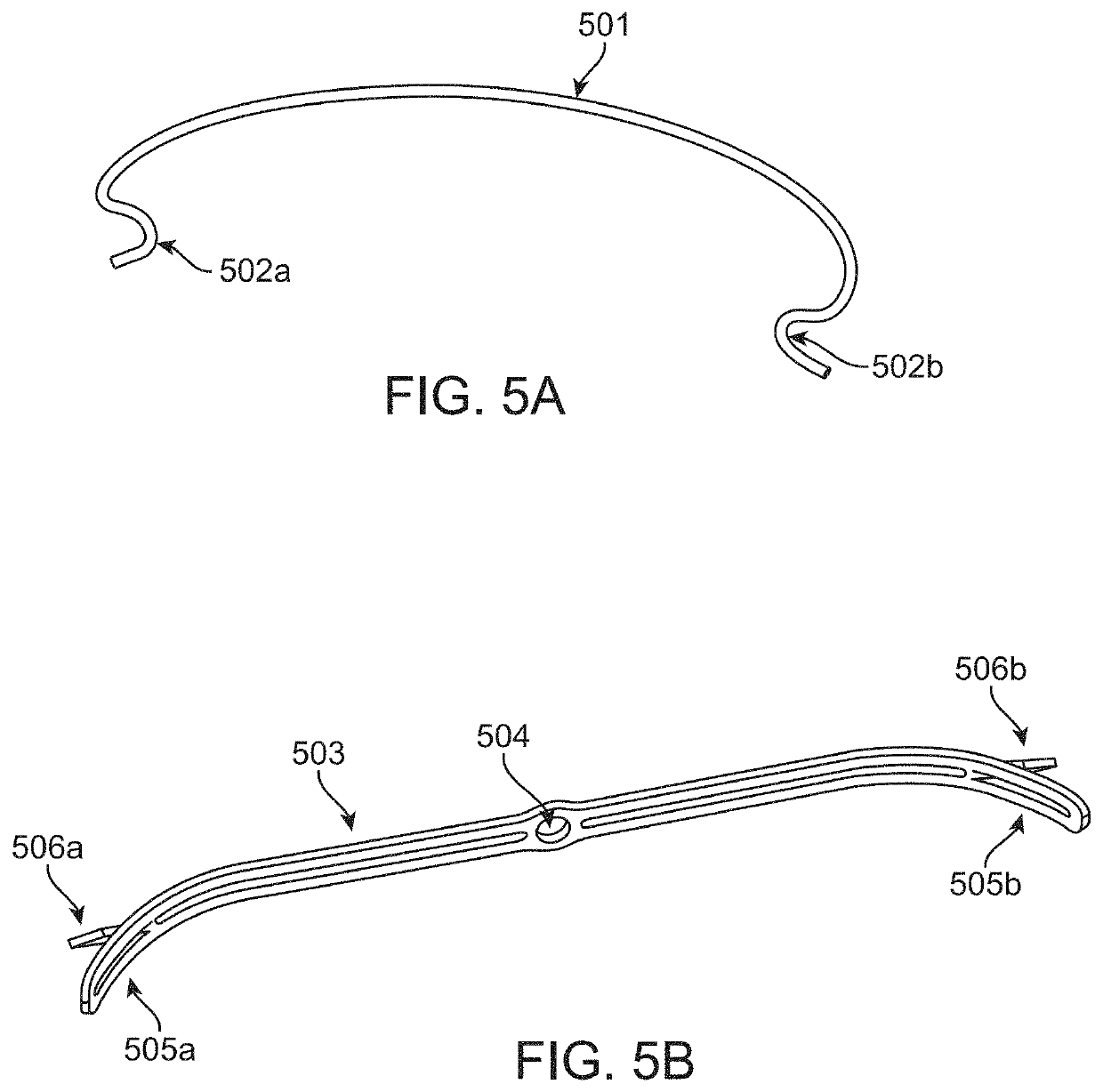
[0432]In a preferred example, the template outline was laser cut from a 0.020″ thick sheet of superelastic Nitinol® to the desired flat shape, which was cleaned and polished by ultrasonic cleaning and manual polishing, then the flat was clamped into a shaping fixture made of heat resistant aluminum that held the flat shape in a configuration with a single concavity and two convexity or apex or convex segment regions, and the heat set assembly was heated to 485° C. for 4 minutes by submerging in a fluidized bed of aluminum oxide, then was rapidly quenched in a room temperature water bath to set the shape. The now preformed shape was removed from the shaping fixture, inspected, cleaned, and finished (by rounding sharp edges with a hand tool), then covered with an ePTFE sleeve, and attached to an anchor in the concavity region.

[0433]In this example, the initial implants were performed via open heart bypass procedure in the ovine model. Templates and anchors were attached to an open sur...


PUM

PropertyMeasurementUnit
Diameteraaaaaaaaaa
Tensionaaaaaaaaaa

Abstract

A system for reshaping a valve annulus includes an elongate template having a length along a longitudinal axis and at least one concavity in a generally lateral direction along said length. The pre-shaped template is positioned against at least a region of an inner peripheral wall of the valve annulus, and at least one anchor on the template is advanced into a lateral wall of the valve annulus to reposition at least one segment of the region of the inner peripheral wall of the valve annulus into said concavity. In this way, a peripheral length of the valve annulus can be foreshortened and/or reshaped to improve coaption of the valve leaflets and/or to eliminate or decrease regurgitation of a valve.

Description

CROSS-REFERENCE TO RELATED APPLICATIONS[0001]This application is a continuation of U.S. patent application Ser. No. 16 / 740,172 (Attorney Docket No. 32016-717.501), filed Jan. 10, 2020, the full disclosure of which application is incorporated herein by reference.[0002]This application is also a continuation-in-part of PCT / US2019 / 032976 (Attorney Docket No. 32016-717.601), filed on May 17, 2019, claiming the benefit of U.S. Provisional Application No. 62 / 767,958 (Attorney Docket No. 32016-717.102), filed Nov. 15, 2018, and of U.S. Provisional Application No. 62 / 673,680 (Attorney Docket No. 32016-717.101), filed May 18, 2018, the full disclosures of which applications are incorporated herein by reference.[0003]This application also claims the benefit of U.S. Provisional Application No. 62 / 937,417 (Attorney Docket No. 32016-717.103), filed Nov. 19, 2019, the full disclosure of which application is incorporated herein by reference.BACKGROUND OF THE INVENTION1. Field of the Invention[0004...

Claims


Application Information

Patent Timeline
IPC IPC(8): A61F2/89A61F2/915A61F2/90
CPCA61F2/89A61F2002/075A61F2/90A61F2/915A61F2/2442A61F2/2445A61F2/2451A61F2220/0016A61F2002/825A61F2002/91558A61F2002/91566A61F2002/91575A61F2002/91591A61F2210/0004A61F2210/0014A61F2210/0076A61F2220/0033A61F2220/0091A61F2230/0006A61F2230/0008A61F2230/001A61F2230/0069A61F2250/0031A61F2250/0036A61F2250/0048A61F2250/0067A61F2250/0071
Inventor SIRHAN, MOTASIMBHAT, VINAYAKPARASCHAC, JOSEPHSERNA, BENJAMYNYAN, JOHN
Owner ELIXIR MEDICAL CORP
Why Eureka
Try Eureka