Apparatus and methods for treating a defective cardiac valve

a technology of cardiac valve and apparatus, which is applied in the field of apparatus and methods for performing transcatheter or minimally invasive repair of a defective cardiac valve, can solve the problems of blood leaking backwards through the valve each, increasing the pressure of blood in the lungs or liver, and reducing forward blood flow, so as to achieve more reliable delivery of the prosthetic device, reduce regurgitation, and reduce the effect of bleeding

Active Publication Date: 2022-01-11
CROIVALVE LTD
View PDF215 Cites 1 Cited by
  • Summary
  • Abstract
  • Description
  • Claims
  • Application Information

AI Technical Summary

Benefits of technology

[0014]The present disclosure provides improved heart valve repair apparatus and methods that, for example, allow more reliable delivery of the prosthetic device to the cardiac valve, provide robust structure, and minimize regurgitation. In accordance with the principles of the present disclosure, the apparatus and methods may be optimized for use in treating cardiac valve regurgitation when the native leaflets of the cardiac valve do not coapt correctly, thus causing blood to leak backwards through the valve as the heart pumps. Advantageously, apparatus of the present disclosure are configured for implantation at a cardiac valve within a blood flow path such that the native leaflets abut the apparatus during the portion of the cardiac cycle when the cardiac valve attempts to close, thereby enhancing native leaflet coaptation and minimizing regurgitation.
[0016]The support may also permit steering of the prosthetic device during delivery for suitable positioning for implantation. The elongated rail of the support is expected to provide enhanced steering although alternative or additional mechanisms may be used such as pull wire steering. The support further allows for extension and telescoping to increase and / or decrease the length of support for suitable positioning of the prosthetic device at the native cardiac valve. For example, the body support catheter may be capable of telescoping to move the prosthetic device into the suitable position within the native cardiac valve.
[0020]Additionally, the body support catheter proximal portion may include a body support catheter pusher that may move the body support catheter lock from the first delivery position where the body support catheter connection is maintained in its collapsed configuration, to the second locked position where the body support catheter lock is positioned over the distal body support locking portion of the body support catheter distal portion to lock the body support catheter distal portion in the implantable configuration. The body support catheter pusher may be retracted proximally to expose the body support catheter connection such that the body support catheter connection may transition from the collapsed or otherwise interlinked configuration to the expanded or otherwise disengaged configuration. When the body support catheter lock is in the second locked position, the body support catheter distal portion locks to the elongated rail distal portion and to the shaping catheter distal portion.
[0035]The outer surface of the prosthetic coaptation body may be formed by an outer skirt. The outer skirt may be made of rigid material or compliant material such as pericardium. The outer skirt may extend around the circumference of the frame to form an outer surface to which the native leaflets coapt when closed during the cardiac cycle. The side walls of the outer skirt may be formed from flexible material to enhance coaptation with the native leaflets when the native leaflets close. The frame also may contain an inner ring that may be located at its proximal end may be roughly concentric with the proximal outer ring. The frame may have predefined kink points to allow for reliable transition from the compressed delivery state into the expanded deployed state. The proximal outer ring, the inner ring, and / or the distal outer ring may exhibit a sinusoidal, triangular or other oscillating shape to further allow reliable compression and expansion.
[0036]The prosthetic coaptation body may include a proximal skirt that is coupled to and fills the space between the inner ring and proximal outer ring. The proximal skirt may be made of rigid material or of compliant material such as pericardium. The proximal skirt and outer skirt may be integrally formed of a single piece of material. The proximal skirt and outer skirt allow the native valves to coapt against the conduit to help prevent regurgitation. Prosthetic leaflets may be coupled to the inner ring thereby forming a valve. The prosthetic leaflets may also be coupled to slotted leaflet mounting features. The prosthetic leaflets are preferably made of compliant material such as pericardium and allow blood to flow distally through the conduit but prevent blood from flowing proximally through the conduit.

Problems solved by technology

Regurgitation occurs when the valve leaflets do not meet, or “coapt” correctly, thus causing blood to leak backwards through the valve each time the heart pumps.
Failure of the valves to prevent regurgitation leads to an increase in the pressure of blood in the lungs or liver and reduces forward blood flow, causing the heart to pump more blood to compensate for the loss of pressure.
Such degradation may result in serious cardiovascular compromise or even death.
These factors lead to poor coaptation of valve leaflets, allowing blood to travel in the wrong direction.
Previously-known valve prostheses have some disadvantages, such as the need for long-term maintenance with blood thinners, the risk of clot formation, limited durability, etc.
However, most dysfunctional valves are too diseased to be repaired using previously known methods and apparatus.
However, these surgeries are prone to many complications and long hospital stays for recuperation.
By expanding the prosthetic valve, the native valve leaflets are generally pushed aside and rendered ineffective.
Such materials, while durable, are prone to blood clotting and thrombus formation, which in turn increases the risk of embolization and stroke or ischemia.
Anticoagulants may be taken to prevent blood clotting that may result in thromboembolic complications and catastrophic heart failure, however, such anti-clotting medication may complicate a patient's health due to the increased risk of hemorrhage.
While iterative improvements have been made on surgical bio-prosthetic valves over the last several decades, existing bio-prosthetic valves still have drawbacks.
One drawback to this procedure is the mismatch in size and mass between opposing surfaces of the stent-like supporting frame.
The mismatch is often due to the variability in the shapes and mechanical characteristics of the stent-like supporting frame.
For prosthetic valves with balloon-expandable stent-like supporting frames, the recoil of the supporting frames post-balloon-inflation may lead to perivalvular leaks around the circumference of the prosthetic valve and potential slippage and migration of the valve post-implantation.
Another risk associated with prosthetic valves having balloon-expandable supporting frames is potential damage to the prosthetic leaflets of the prosthesis during implantation, when the prosthetic leaflets may be compressed between the balloon and the supporting frame.
For prosthetic valves with self-expanding stent-like supporting frames, mismatch may arise due to the deformation / movement of the supporting frame, e.g., slight deformation of the frame into a less than circular shape during normal cardiac movement.
Such mismatch may lead to instability among components of a prosthetic valve, resulting in perivalvular leaks and uneven stress distribution in the prosthetic leaflets, resulting in accelerated wear of the valve.
Though the plug design helps to prevent regurgitation, the major drawback is that it also blocks some of the blood flow during diastole.

Method used


Image

  • Apparatus and methods for treating a defective cardiac valve
  • Apparatus and methods for treating a defective cardiac valve
  • Apparatus and methods for treating a defective cardiac valve

Examples


Embodiment Construction

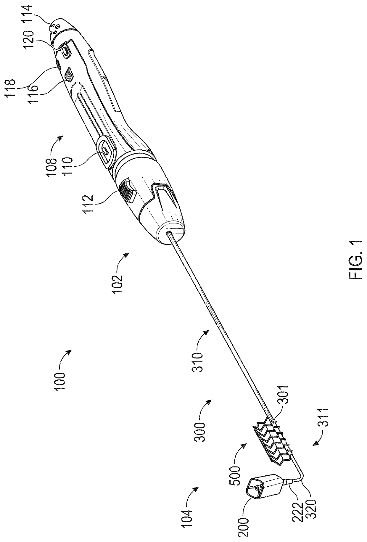
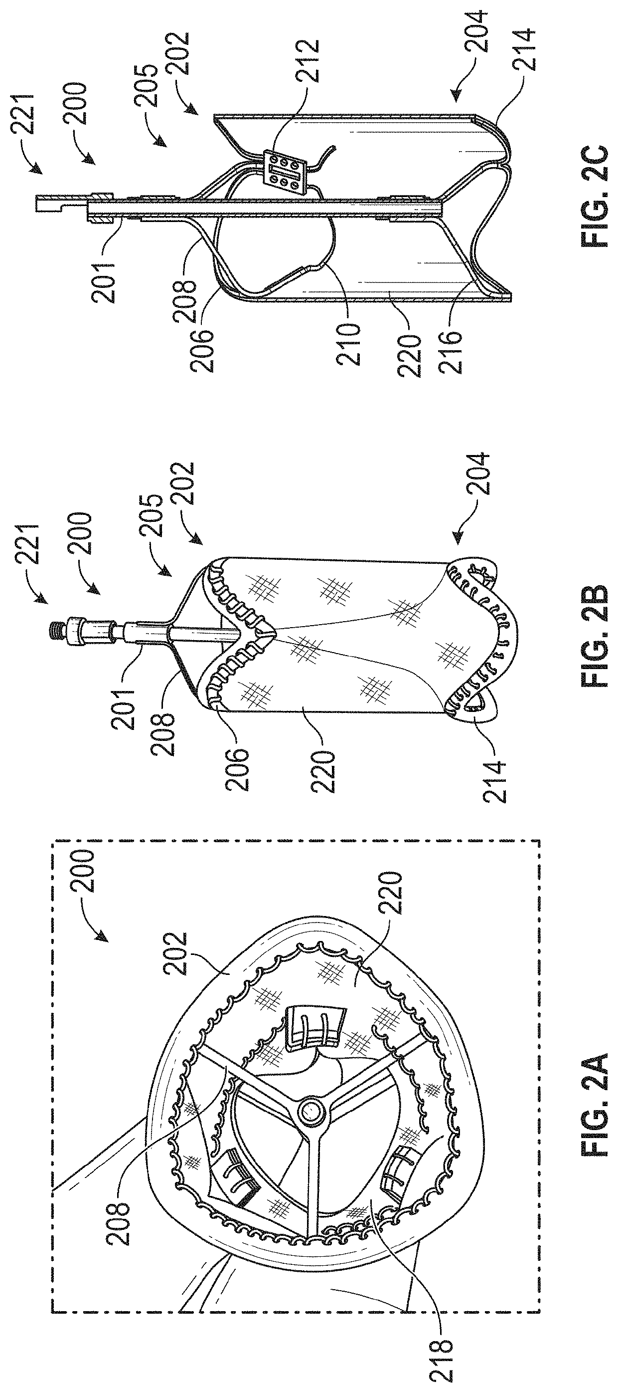
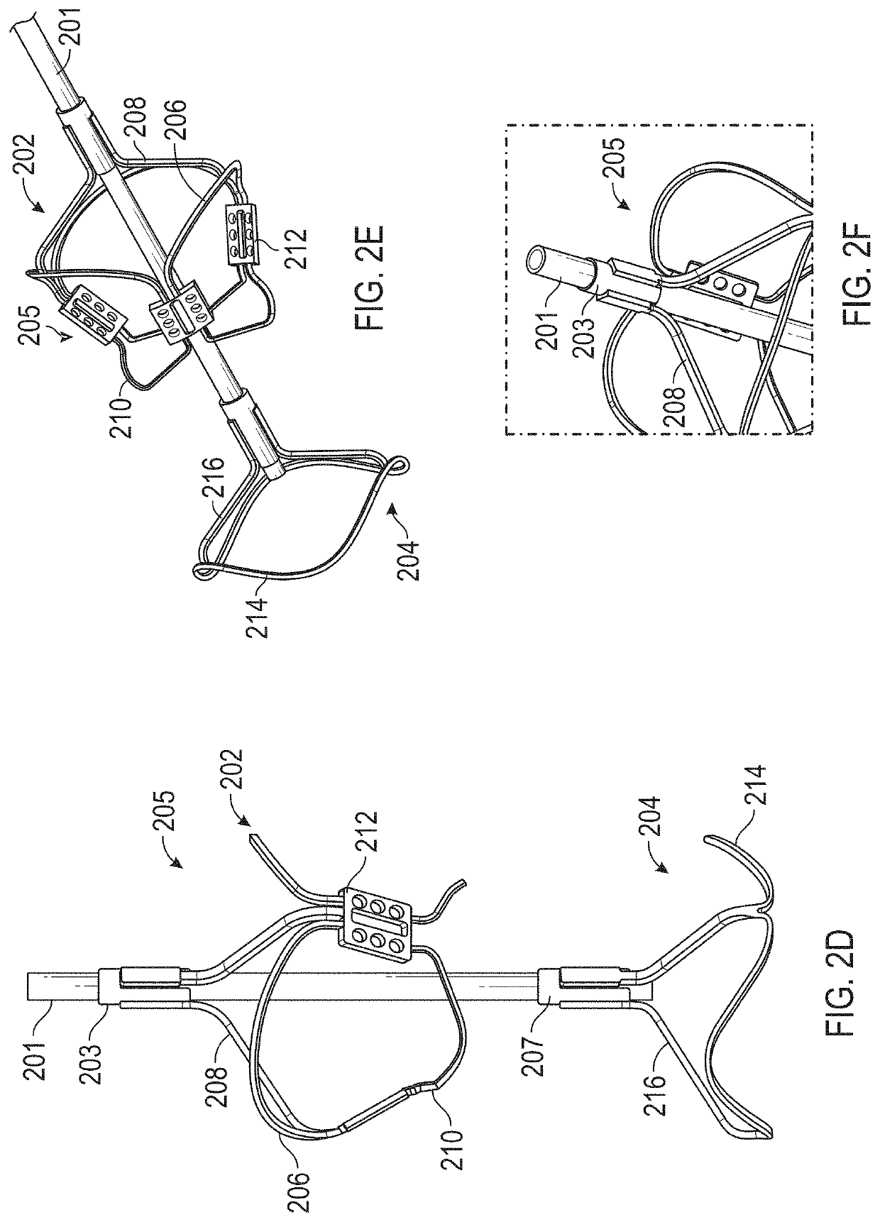
[0090]Embodiments of the present invention are directed to exemplary systems and methods for reducing cardiac valve regurgitation. Provided herein is a prosthetic device that may contain a prosthetic coaptation body to be positioned at a native cardiac valve. The prosthetic device may be suspended across the native heart valve by a support. For example, the support may be coupled to the prosthetic coaptation body and extend out of the heart into an adjacent blood vessel coupled to the heart (e.g., superior vena cava, inferior vena cava). The support may be coupled to the blood vessel with an anchor that preferably is expandable and has a stent structure. In some examples, the support is structured to suspend the prosthetic coaptation body in the native valve in a free-standing manner without anchoring to cardiac tissue, thereby minimizing damage to the heart. The prosthetic coaptation body may be formed from a frame (e.g., metal frame such as Nitinol) that is at least partially cove...


PUM


Abstract

Apparatus and methods for repairing a cardiac valve, e.g., a tricuspid valve, are provided. The apparatus may include a prosthetic device coupled to an elongated support to suspend and maintain the prosthetic device within the cardiac valve. The support may include a proximal elongated shaft detachably coupled, in a delivery state, to a distal elongated shaft coupled to the prosthetic device. The proximal elongated shaft may detach from the distal elongated shaft at a detachment area within the patient responsive to actuation and components of the distal elongated shaft may lock to implant the prosthetic device and the distal elongated shaft within the patient. The prosthetic device may be formed of biocompatible material coupled to a frame, and may have prosthetic leaflets that allows blood to flow through in one direction during a phase of the cardiac cycle (e.g., diastole) but prevent blood regurgitation during the other phase (e.g., systole).

Description

CROSS-REFERENCE TO RELATED APPLICATIONS[0001]This application is a continuation of International PCT Patent Application Serial No. PCT / IB2020 / 057368, filed Aug. 4, 2020, which claims the benefit of priority to U.S. Provisional Patent Application No. 62 / 882,961, filed Aug. 5, 2019, the entire contents of each of which are incorporated herein by reference.FIELD OF THE INVENTION[0002]This application generally relates to apparatus and methods for performing transcatheter or minimally invasive repair of a defective cardiac valve, such as the tricuspid, mitral, pulmonary, and aortic valves.BACKGROUND OF THE INVENTION[0003]The human heart has four major valves which moderate and direct blood flow in the cardiovascular system. These valves serve critical functions in assuring a unidirectional flow of an adequate blood supply through the cardiovascular system. The mitral valve and aortic valve control the flow of oxygen-rich blood from the lungs to the body. The mitral valve lies between th...

Claims


Application Information

Patent Timeline
Patent Type & Authority Patents(United States)
IPC IPC(8): A61F2/24
CPCA61F2/2466A61F2/243A61F2/2418A61F2/2427A61F2/2439A61F2220/0016A61F2/246A61F2220/0008A61F2220/0091A61F2250/006A61F2250/0004
Inventor VESELY, IVANQUINN, CONORMULLIGAN, AOIFEHENEGHAN, PAULQUINN, PATRICKO'SULLIVAN, STEPHEN
Owner CROIVALVE LTD
Why Eureka
Try Eureka