
Automatic tin soldering mechanism of coil conductive assembly of low-voltage circuit breaker and welding system of coil conductive assembly of low-voltage circuit breaker

A low-voltage circuit breaker and conductive component technology, applied in auxiliary devices, welding equipment, metal processing, etc., can solve the problems of low welding quality of conductive component products, high production costs, low work efficiency, etc. Welding deformation can not be assembled, high production efficiency, eliminating the effect of welding inclination and tin leakage

Active Publication Date: 2017-12-05
YUEQING YEDAO ELECTROMECHANICAL CO LTD
View PDF5 Cites 8 Cited by
  • Summary
  • Abstract
  • Description
  • Claims
  • Application Information

AI Technical Summary

Problems solved by technology

[0007] The purpose of the present invention is to provide an automatic soldering mechanism for coil conductive components of low-voltage circuit breakers, which solves the problems of low welding quality of finished conductive components, high production costs and low work efficiency in the prior art using manual or semi-manual welding equipment

Method used


Image

  • Automatic tin soldering mechanism of coil conductive assembly of low-voltage circuit breaker and welding system of coil conductive assembly of low-voltage circuit breaker
  • Automatic tin soldering mechanism of coil conductive assembly of low-voltage circuit breaker and welding system of coil conductive assembly of low-voltage circuit breaker
  • Automatic tin soldering mechanism of coil conductive assembly of low-voltage circuit breaker and welding system of coil conductive assembly of low-voltage circuit breaker

Examples


Embodiment Construction

[0035] The front and rear positions in the text are based on the orientation of the drawings, and the actual installation position is analogous.

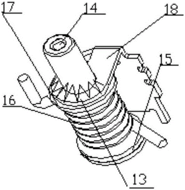
[0036] Such as figure 1 As shown, the assembly and welding object of the device of the present invention is a conductive component used in a low-voltage circuit breaker, and its structure is to include an oil cup 14, and the large end section of the oil cup 14 is a disc-shaped pole shoe with an inverted T-shaped structure. The outer circumference of the oil cup 14 is sequentially set with a multi-layer annular paper lower gasket 15 (2 in total), a multi-turn coil 16, a multi-layer annular paper upper gasket 17, and an inverted L-shaped structure. The yoke 18 is soldered to form a weld 131 with a triangular cross-section. The maximum thickness of the weld 131 is 2 mm, and the extension length of the weld 131 is not less than 1 / 3 of a circle along the circumference.

[0037] The device of the present invention is to automatically ass...


PUM


Abstract

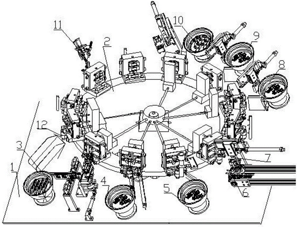
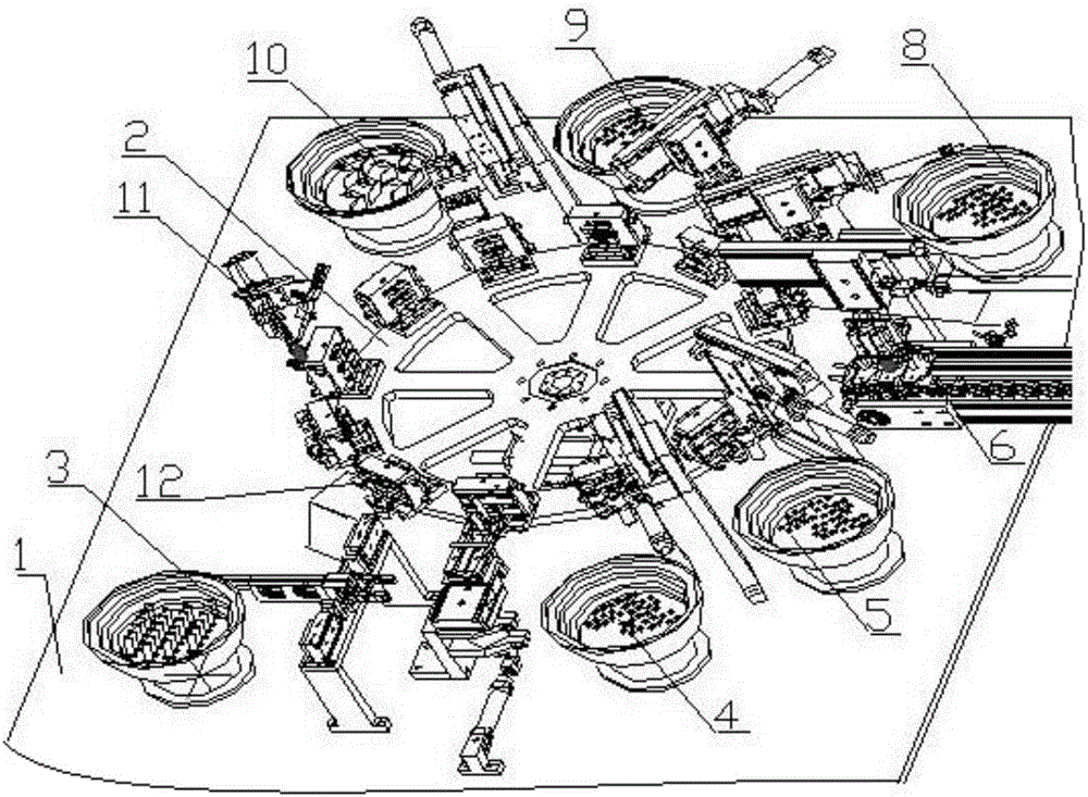
The invention discloses an automatic tin soldering mechanism of a coil conductive assembly of a low-voltage circuit breaker and further discloses a welding system of the coil conductive assembly of the circuit breaker. The welding system of the coil conductive assembly of the circuit breaker comprises a rotating disk assembly. The rotating disk assembly is arranged on a horizontal tabletop. Nine feeding and discharging mechanisms and three detectors are sequentially arranged on the horizontal tabletop around the periphery of the rotating disk assembly. The rotating disk assembly comprises an inner disk and an outer rotating disk. Twelve stations are evenly arranged on the outer rotating disk and are close to the outer side in the circumference direction. The inner disk is provided with eight station starting mechanisms used for driving station clamps to be opened or closed in the circumferential direction. Each station starting mechanisms is connected with a station starting transmission mechanism through a connection rod. The twelve stations are each provided with a station clamp. The twelve station clamps are evenly arranged on the outer rotating disk and are close to the outer side of the outer rotating disk, and the twelve station clamps correspond to the nine feeding and discharging mechanisms surrounding the outer circumference of the rotating disk assembly in position. The welding system of the coil conductive assembly of the low-voltage circuit breaker is compact in structure, reliable in work and high in welding quality.

Description

technical field [0001] The invention belongs to the technical field of assembly and welding of electrical components, and relates to an automatic soldering mechanism for a low-voltage circuit breaker coil conductive component, and also relates to a circuit breaker coil conductive component welding system. Background technique [0002] The existing soldering is mainly spot welding and linear drag welding. For the assembly and welding of the oil cup and the yoke components, or the small-sized oil cup and the yoke coil of the arc weld, only manual spot welding can be used. The method is to weld one point by one point, and form the weld seam required by the product through multiple multi-pass spot welding connections. The main problems are as follows: [0003] 1) One worker performs flow welding in two sections, which cannot complete the complete butt joint of the weld seam. There are always unconnected parts in the butt joint part of the weld seam, or it is uneven and not smoot...

Claims


Application Information

Patent Timeline
IPC IPC(8): B23K3/00B23K3/08
CPCB23K3/00B23K3/08
Inventor 不公告发明人
Owner YUEQING YEDAO ELECTROMECHANICAL CO LTD
Learn More