

Double-layer pipeline compensation connector
A double-layer pipe and connector technology, which is applied in the direction of adjustable connection, sleeve/socket connection, pipe/pipe joint/pipe fitting, etc., can solve problems such as pipeline damage, reduce the cost of construction and user costs, and significantly save money advantage effect
- Summary
- Abstract
- Description
- Claims
- Application Information
AI Technical Summary
Problems solved by technology
Method used
Image

Examples
Embodiment 1
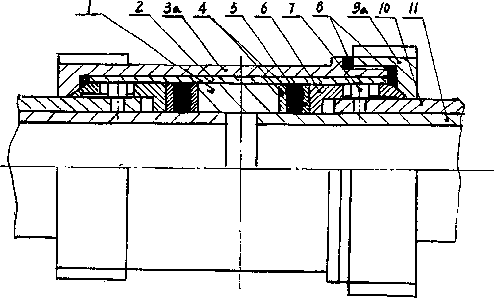
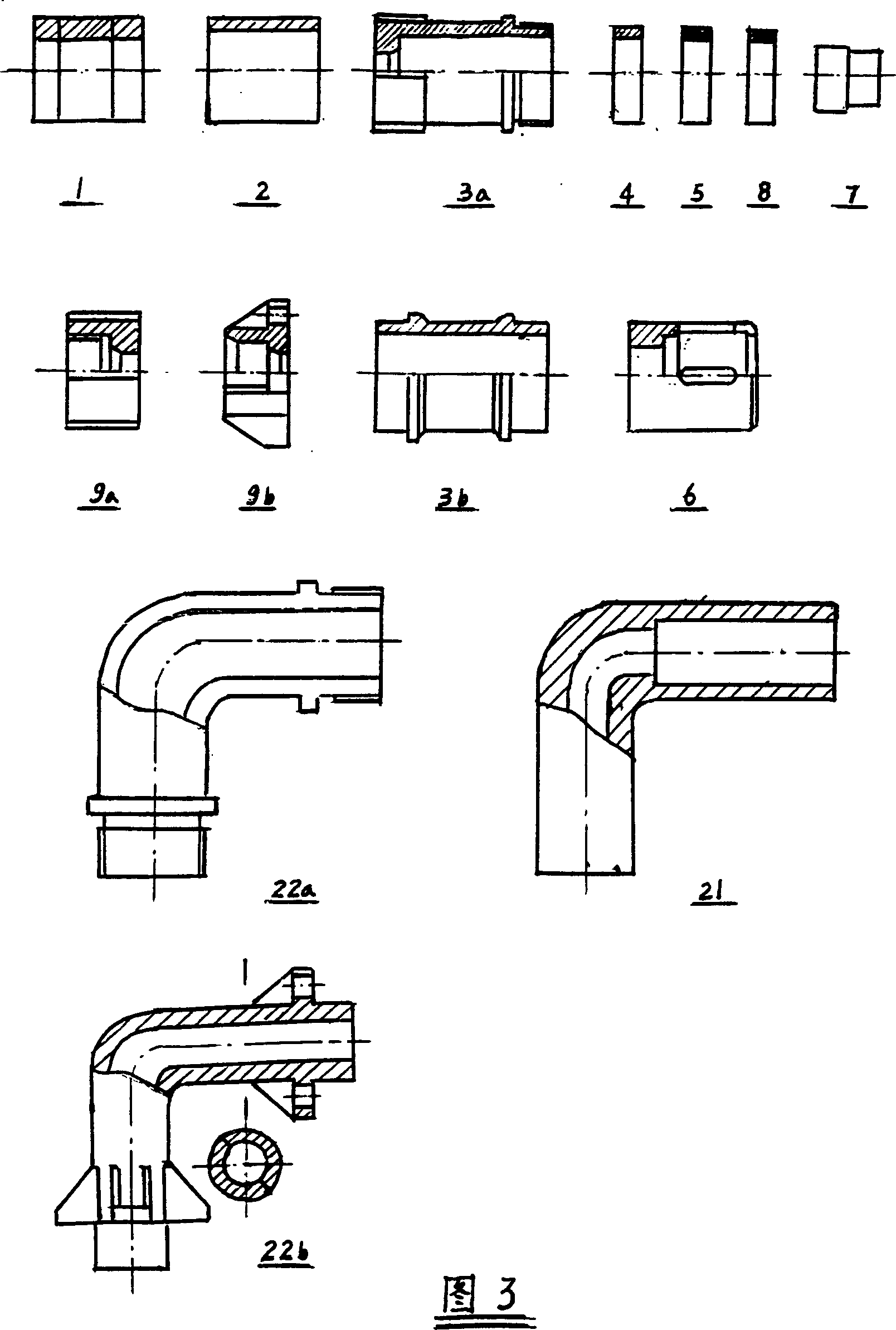
[0026] For the installation and use of threaded straight-through double-layer pipeline compensation connector, see figure 1 , first push the inner pipe into the outer pipe for a certain length, so as not to affect the hole drilling, and then use a special tool to position and process the hole or hole on the outer circle of the end of the outer pipe, then restore the inner pipe to the original extension length, and then place the installed The nut cover 9a and the brake sleeve 6 with the anticorrosion ring 8 are inserted into the outer circle of the outer pipeline 10 of a double-layer pipeline successively, and then the threaded sleeve 3a and the brake sleeve 6 with the anticorrosion ring 8 and the sealing pipe 2 are housed, Insert the outer circle of the outer pipe 10 of another double-layer pipe successively, and then insert the sealing ring 4, the sealing ring 5, and the sealing ring 4 into the outer circle of the inner pipe 11 of the two double-layer pipes respectively, and ...
Embodiment 2
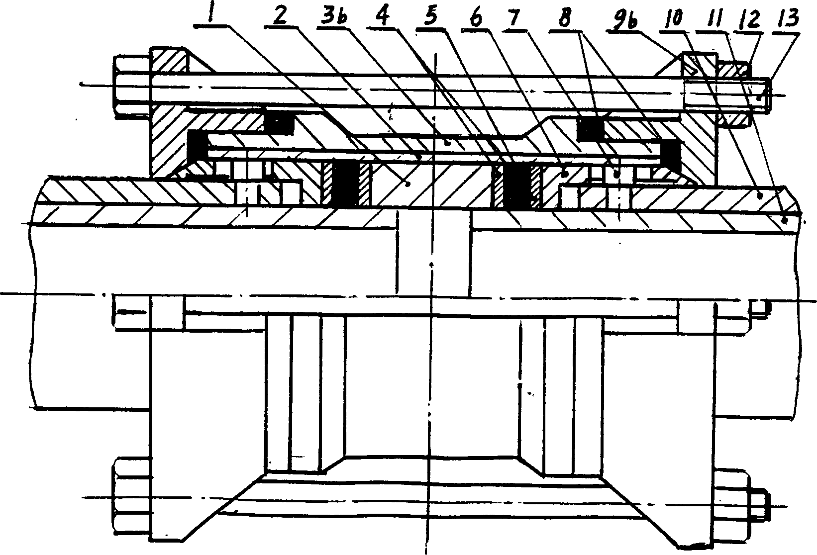
[0028] The installation and use of bolted straight-through double-layer pipeline compensation connector figure 2 , same earlier outer pipe 10 ends outer circular pipe wall, after positioning processing hole or hole, then restore the original extension length of inner pipe, then, a clamping sleeve 9b with anticorrosion ring 8, brake sleeve 6 1. The overcoat 3b with the sealing tube 2 is inserted into the outer circle of the outer pipeline 10 of a double-layer pipeline successively, and the other clamping sleeve 9b and the brake sleeve 6 equipped with the anti-corrosion ring 8 are inserted into the other successively. The outer circle of the outer pipe 10 of a double-layer pipe is then inserted into the outer circle of the inner pipe 11 of the two double-layer pipes in turn, respectively, with the sealing ring 4, the sealing ring 5, and the sealing ring 4, and then the middle sleeve 1 is inserted into the The outer circles of the two inner pipes 11 are glued with sticky substan...
Embodiment 3
[0030] The installation and use of the threaded elbow double-layer pipeline compensation connector Figure 4 Similarly, after the outer pipe wall at the end of the outer pipe 10 is positioned to process the recess or hole, the inner pipe 11 is restored to the original extension length, and then the nut sleeve 9a and the brake sleeve 6 equipped with the anti-corrosion ring 8 are successively Insert the outer circle of the outer pipe 10 of a double-layer pipe, then stick the viscous substance with the brake nail 7, pass the pipe wall hole on the brake sleeve 6, and position the outer pipe wall hole or the concave hole of the outer pipe 10. In the cave, one end of the curved sealing tube 21 equipped with the middle sleeve 1, the sealing ring 4, the sealing ring 5 and the sealing ring 4 is inserted into the outer circle of the inner pipe 11 and the outer circle of the brake sleeve 6, and then the other pair of Carry out the same operation with the other end of the layered pipeline...
PUM
 Abstract
Description
Claims
Application Information