Fluid Transfer Pipe With Corrugated Portion(s) and Method for Manufacturing Same

a technology of transfer pipe and corrugated portion, which is applied in the direction of pipes, mechanical equipment, other domestic objects, etc., can solve the problems of elongation of the reliefs in the axial direction of the pipe, and the flattening of the reliefs

Active Publication Date: 2012-04-12
HUTCHINSON SRL
View PDF12 Cites 6 Cited by
  • Summary
  • Abstract
  • Description
  • Claims
  • Application Information

AI Technical Summary

Benefits of technology

[0006]One aim of the present invention is to propose a fluid transfer pipe in particular for filling a cooling circuit of a motor vehicle heat engine which makes it possible to remedy these drawbacks, this pipe comprising at least one single-layer or multilayer corrugated bendable portion which is based on at least one thermoplastic material and which comprises a succession of radial reliefs which are axially spaced so as to form hollows between them, each relief having two frontal regions linked together by an intermediate region, the frontal regions of each relief each having one and the same overall polygonal contour defining at least three straight sections interlinked by rounded sections, and the contours of these successive reliefs being adapted to allow for the stripping of said at least one corrugated portion from two hemicylindrical shells of a mould along a single axial stripping plane.

Problems solved by technology

A major drawback in the known corrugated thermoplastic pipes lies in these rounded geometries for the contours of these annular reliefs which, if they favour the flexibility of the pipe for its displacements, have the undesirable effect of resulting in a flattening and therefore an elongation of these reliefs in the axial direction of the pipe, because of the high operating temperatures and / or pressures.

Method used


Image

  • Fluid Transfer Pipe With Corrugated Portion(s) and Method for Manufacturing Same
  • Fluid Transfer Pipe With Corrugated Portion(s) and Method for Manufacturing Same
  • Fluid Transfer Pipe With Corrugated Portion(s) and Method for Manufacturing Same

Examples


Embodiment Construction

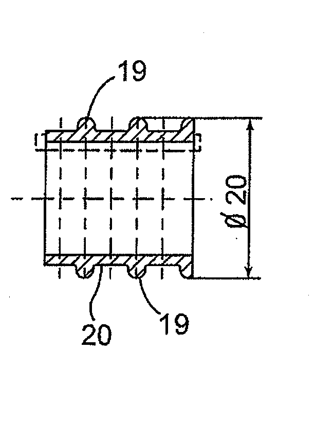
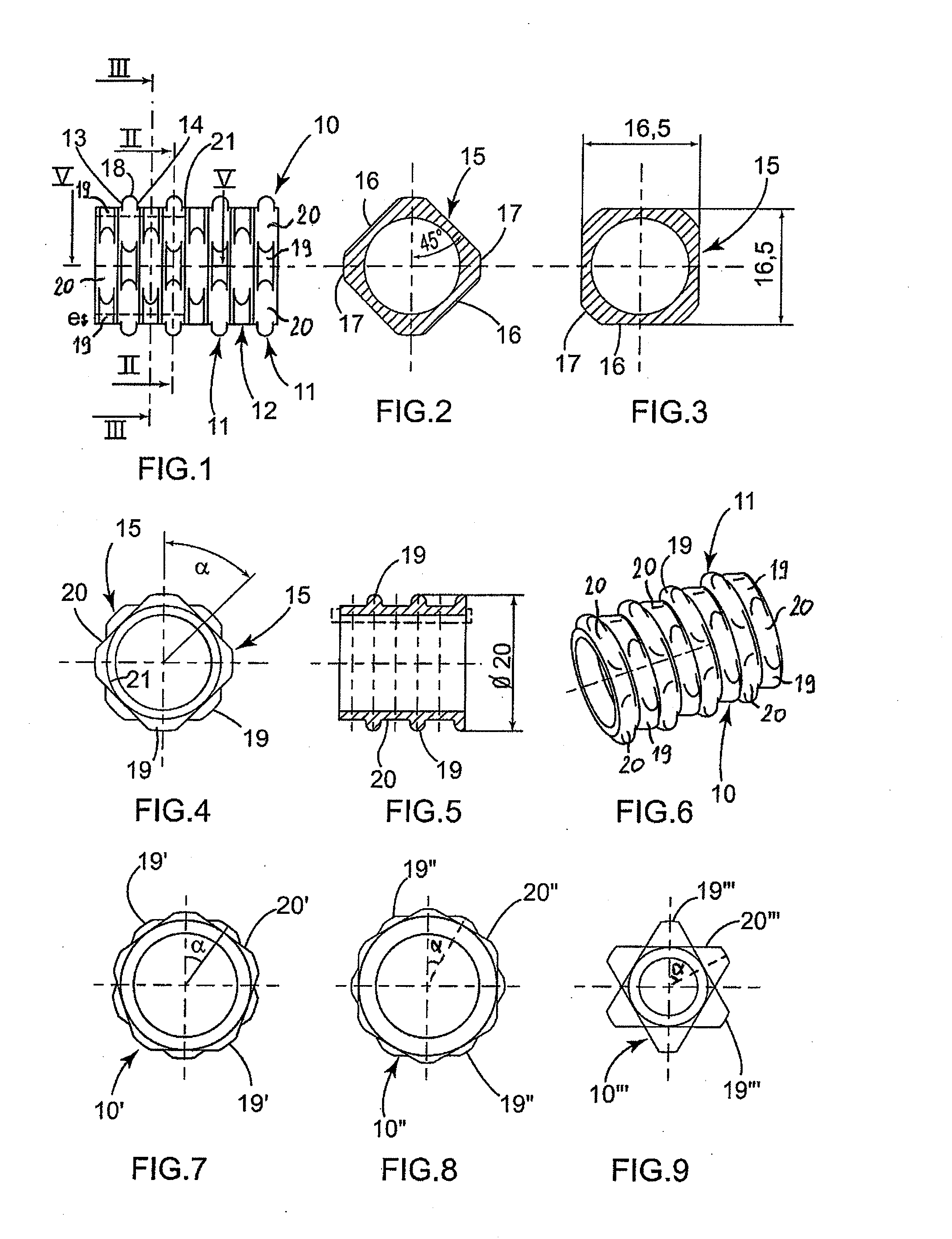
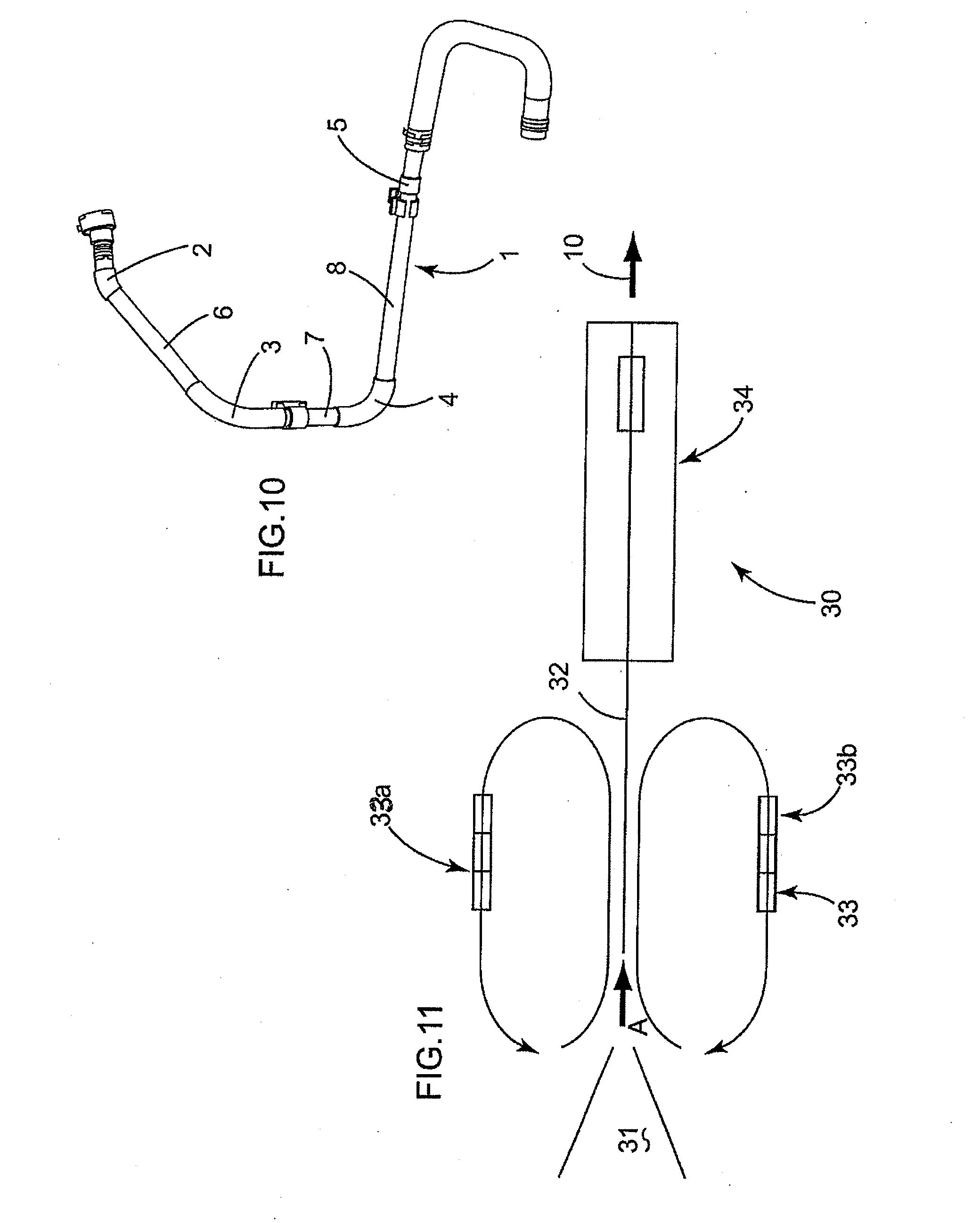
[0043]A pipe 1 according to the invention is illustrated in FIG. 10, this pipe preferably being made by an extrusion blow-moulding of at least one thermoplastic material and comprising in this example a number of corrugated and bent or bendable portions 2, 3, 4, 5 which are interlinked by smooth and straight portions 6, 7, 8 and each of which can be seen precisely in FIGS. 1 to 9. This pipe 1 is of single-layer or multilayer type, being able to comprise in the latter case a radially internal layer based on a thermoplastic elastomer, such as a TPV, and a radially outer layer based on a plastomer, such as a polyamide, as a non-limiting example.

[0044]As can be seen in FIGS. 1, 5 and 6, each corrugated portion 2 to 5 of the pipe 1 defines a tubular structure 10 having a plurality of radial reliefs 11 which follow one another axially by being separated in pairs from one another by substantially flat hollows 12 and which are each discontinuous in the circumferential direction. More specif...


PUM

PropertyMeasurementUnit
angle of offsetaaaaaaaaaa
distanceaaaaaaaaaa
thicknessaaaaaaaaaa

Abstract

The invention provides a fluid transfer pipe for filling a cooling circuit of a motor vehicle, and the method for manufacturing said pipe. This pipe includes at least one corrugated bendable portion based on at least one thermoplastic material and which includes a succession of radial reliefs axially spaced so as to form hollows between them, each relief having two frontal regions linked together by an intermediate region, the frontal regions of each relief each having one and the same overall polygonal contour defining at least three straight sections forming flats for this relief and interlinked by rounded sections forming bulges, and the contours of the successive reliefs being adapted to allow for the stripping of the corrugated portion from two hemicylindrical shells of a mould along a single axial stripping plane.

Description

FIELD OF THE INVENTION[0001]The present invention relates to a fluid transfer pipe in particular for filling a motor vehicle cooling circuit, this pipe comprising at least one corrugated bendable portion, and a method for manufacturing this pipe. The invention applies generally to bendable pipes made of at least one thermoplastic material and being able to transfer all liquid fluids (e.g. water or a coolant for heat engine) or gaseous fluids (e.g. air).BACKGROUND[0002]As is known, the motor vehicle manufacturers demand that the cooling circuit filling pipes should withstand displacements in all three directions as well as vibrations, which is obtained by the presence of undulations or corrugations defining reliefs and hollows on the outer face of these pipes, which are conventionally made of rubber for reasons of flexibility in response to the displacements, and of resistance to the fluid conveyed and to its temperature and circulation pressure.[0003]Recently, and in particular for ...

Claims


Application Information

Patent Timeline
Patent Type & Authority Applications(United States)
IPC IPC(8): F16L11/00B29C49/04B29C48/09B29C48/13B29C48/30
CPCF16L11/15B29C47/0021B29C47/126B29C49/0021B29K2021/003B29K2023/06F16L11/111B29K2067/003B29K2067/006B29K2075/00B29K2077/00B29L2023/183B29L2023/22B29K2027/18B29C48/08B29C48/303B29C48/13B29C48/09
Inventor BERTERO, LUCIANOROBASTO, MARIOJEANSON, ROMAINRAMARO, CLAUDIO
Owner HUTCHINSON SRL
Why Eureka
Try Eureka