Image forming apparatus

Inactive Publication Date: 2012-04-12
CANON KK
View PDF8 Cites 0 Cited by
  • Summary
  • Abstract
  • Description
  • Claims
  • Application Information

AI Technical Summary

Problems solved by technology

However, the pressing force becomes weak at the center part range.
Consequently, there occurs difference in fixing capability of the toner image to the sheet between a sheet portion passing through the center part range and sheet portions passing through the both end part ranges of the pair of rollers.

Method used


Image

  • Image forming apparatus
  • Image forming apparatus
  • Image forming apparatus

Examples


first embodiment

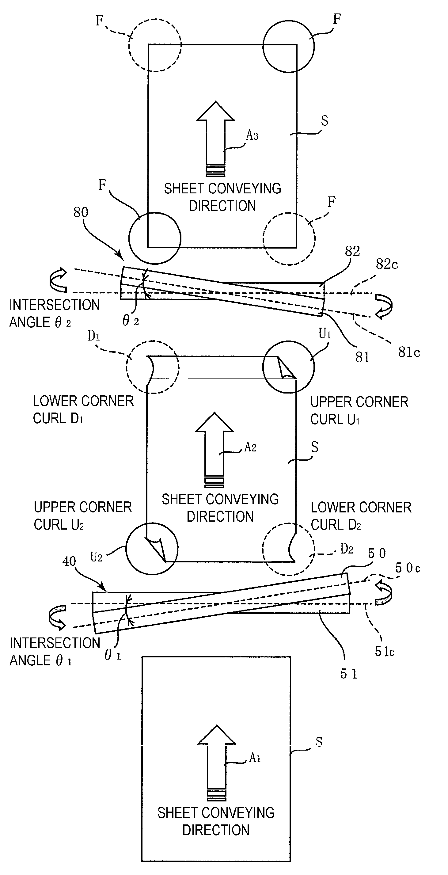
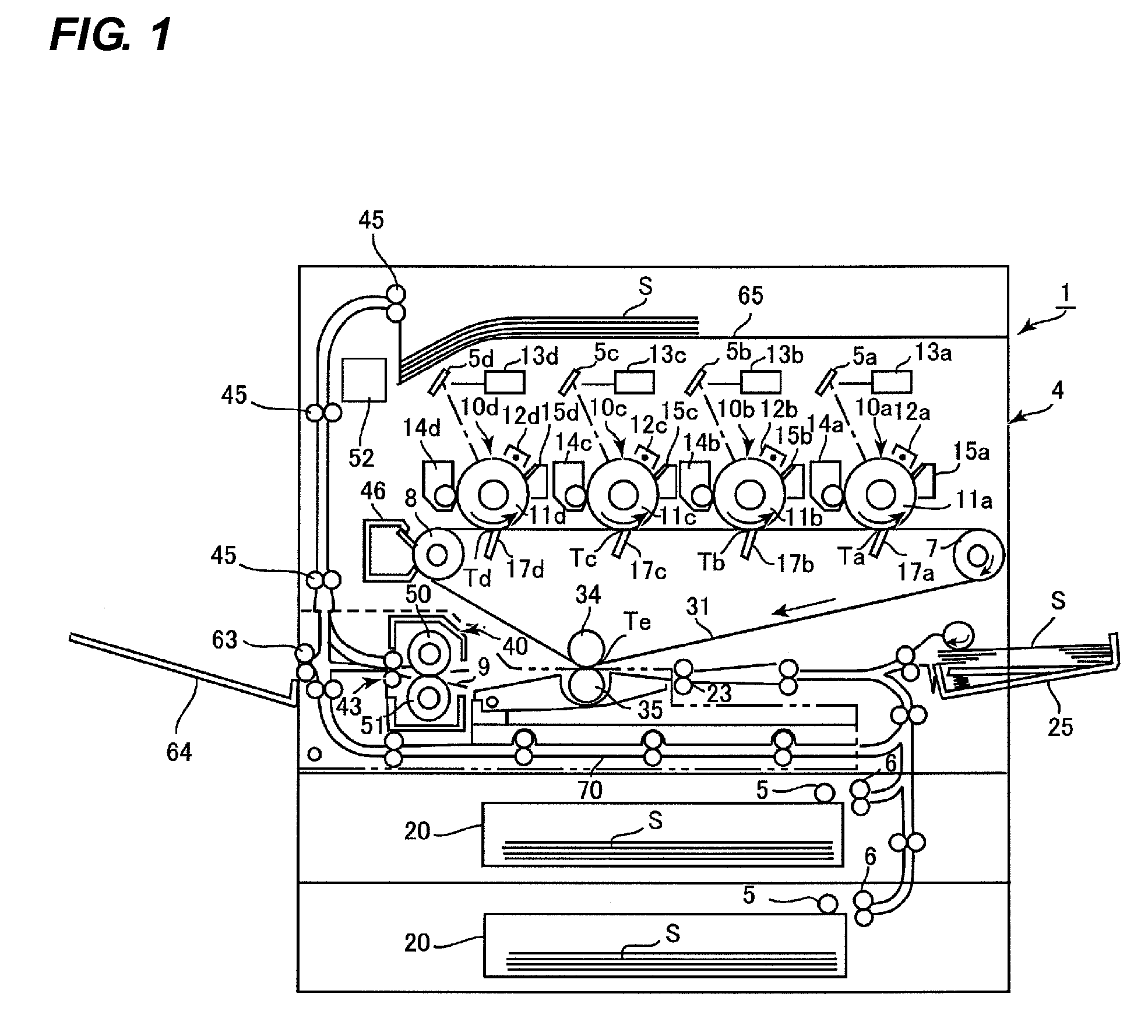
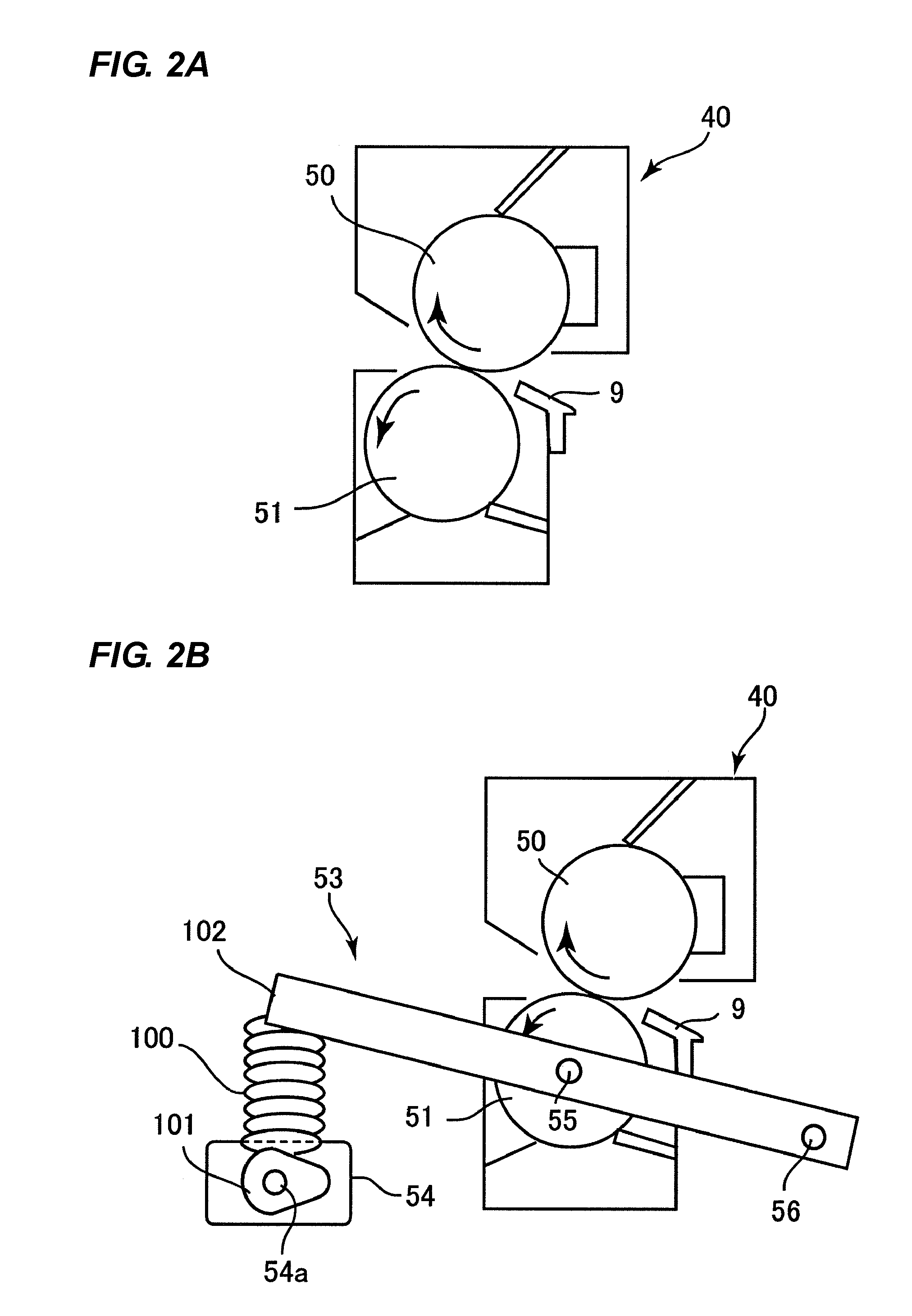
[0023]First, a whole structure of an image forming apparatus according to the first embodiment will be described with reference to FIG. 1. FIG. 1 is a sectional view of an image forming apparatus 1 according to the present embodiment such as a color electrophotographic printer as being sectioned along a sheet conveying direction.

[0024]As illustrated in FIG. 1, in the image forming apparatus 1, image forming portions 10d, 10c, 10b, 10a which form images of yellow, magenta, cyan and black are arranged along an intermediate transfer belt 31 which is arranged at a center part of an apparatus main body. In the image forming portion 10d of yellow, a yellow toner image formed on a photosensitive drum 11d is primarily transferred to the intermediate transfer belt31 at a primary transfer portion Td. In the image forming portion 10c of magenta, a magenta toner image formed on a photosensitive drum 11c is primarily transferred as being superimposed with the yellow toner image on the intermedia...

second embodiment

[0054]Next, the second embodiment according to the present invention will be described with reference to FIGS. 5 to 7. First, a whole structure of an image forming apparatus 21 according to the present embodiment will be described with reference to FIG. 5. FIG. 5 is a sectional view schematically illustrating the whole structure of the image forming apparatus 21.

[0055]In the image forming apparatus 21, laser is irradiated respectively from laser scanning units 37a, 37b, 37c, 37d of which light source is semiconductor laser onto surfaces of photosensitive drums 32a, 32b, 32c, 32d of respective colors of yellow, magenta, cyan and black. With this structure, an electrostatic latent image is formed on each surface of the photosensitive drums 32a to 32d. From the respective electrostatic latent images formed at the photosensitive drums 32a to 32d, toner images are produced as the electrostatic latent images are developed respectively by development units 38a to 38d. The toner images of t...


PUM


Abstract

The present invention provides an image forming apparatus capable of appropriately curing curl which is apt to be generated at a fixing-completed sheet.An intersection angle θ2 between respective axis lines 81c, 82c of an upper conveying roller 81 and a lower conveying roller 82 in a conveying apparatus 80 is set to be in the opposite direction to an intersection angle θ1 between respective axis lines 50c and 51c of a fixing roller 50 and a pressure roller 51 in the fixing apparatus 40. Accordingly, curl generated at a sheet S at the time of pressure fixing at the fixing apparatus 40 can be returned into a state before fixing as being appropriately corrected in the opposite direction by the upper conveying roller 81 and the lower conveying roller 82.

Description

BACKGROUND OF THE INVENTION[0001]1. Field of the Invention[0002]The present invention relates to an image forming apparatus including a fixing apparatus which pressurizes and fixes a toner image transferred to a sheet onto the sheet, more specifically, relates to an image forming apparatus including a structure to correct (i.e., cure) curl of a sheet generated in the fixing apparatus.[0003]2. Description of the Related Art[0004]In general, in a case where an image is printed on a sheet with an image forming apparatus, the sheet to which a toner image is transferred by a transfer medium such as a photosensitive drum and an intermediate transfer belt is conveyed to a fixing apparatus at which the toner image is fixed, and then, is conveyed to a discharge portion.[0005]By the way, there is a fixing apparatus including a pair of rollers including a fixing roller and a pressure roller which is arranged as being faced to the fixing roller in a manner of being pressed thereto. Here, there ...

Claims


Application Information

Patent Timeline
IPC IPC(8): G03G15/20
CPCG03G15/206G03G15/6576
Inventor NAGATA, TEPPEI
Owner CANON KK
Why Eureka
Try Eureka