Efficient address assignment in coded lighting systems

Active Publication Date: 2012-04-19
KONINKLIJKE PHILIPS ELECTRONICS NV
View PDF8 Cites 61 Cited by
  • Summary
  • Abstract
  • Description
  • Claims
  • Application Information

AI Technical Summary

Benefits of technology

[0010]It is an object of the present invention to overcome the problems discussed above, and to provide improved means for operating a lighting system.

Problems solved by technology

The size of the required address space makes that the preferred CL modulation techniques, such as code division multiple access (CDMA) and frequency division multiple access (FDMA), cannot be applied efficiently.
This is caused by the fact that these are typically limited to, due to practical implementation issues, much smaller number of unique codes or frequencies, for CDMA and FDMA, respectively.
When worldwide or control network wide unique, and consequently long, addresses or codes are applied, however, efficient CL modulation methods cannot be applied to their best extent.
This results in a long response time of the system, which might turn out to be unacceptable for some applications.
Also, the suboptimal assignment of addresses or codes between the light sources might result in decreased performance in illumination contribution estimation.

Method used


Image

  • Efficient address assignment in coded lighting systems
  • Efficient address assignment in coded lighting systems
  • Efficient address assignment in coded lighting systems

Examples


Embodiment Construction

[0043]The present invention will now be described more fully hereinafter with reference to the accompanying drawings, in which certain embodiments are shown. This invention may, however, be embodied in many different forms and should not be construed as limited to the embodiments set forth herein; rather, these embodiments are provided by way of example so that this disclosure will be thorough and complete, and will fully convey the scope of the invention to those skilled in the art. Like numbers refer to like elements throughout.

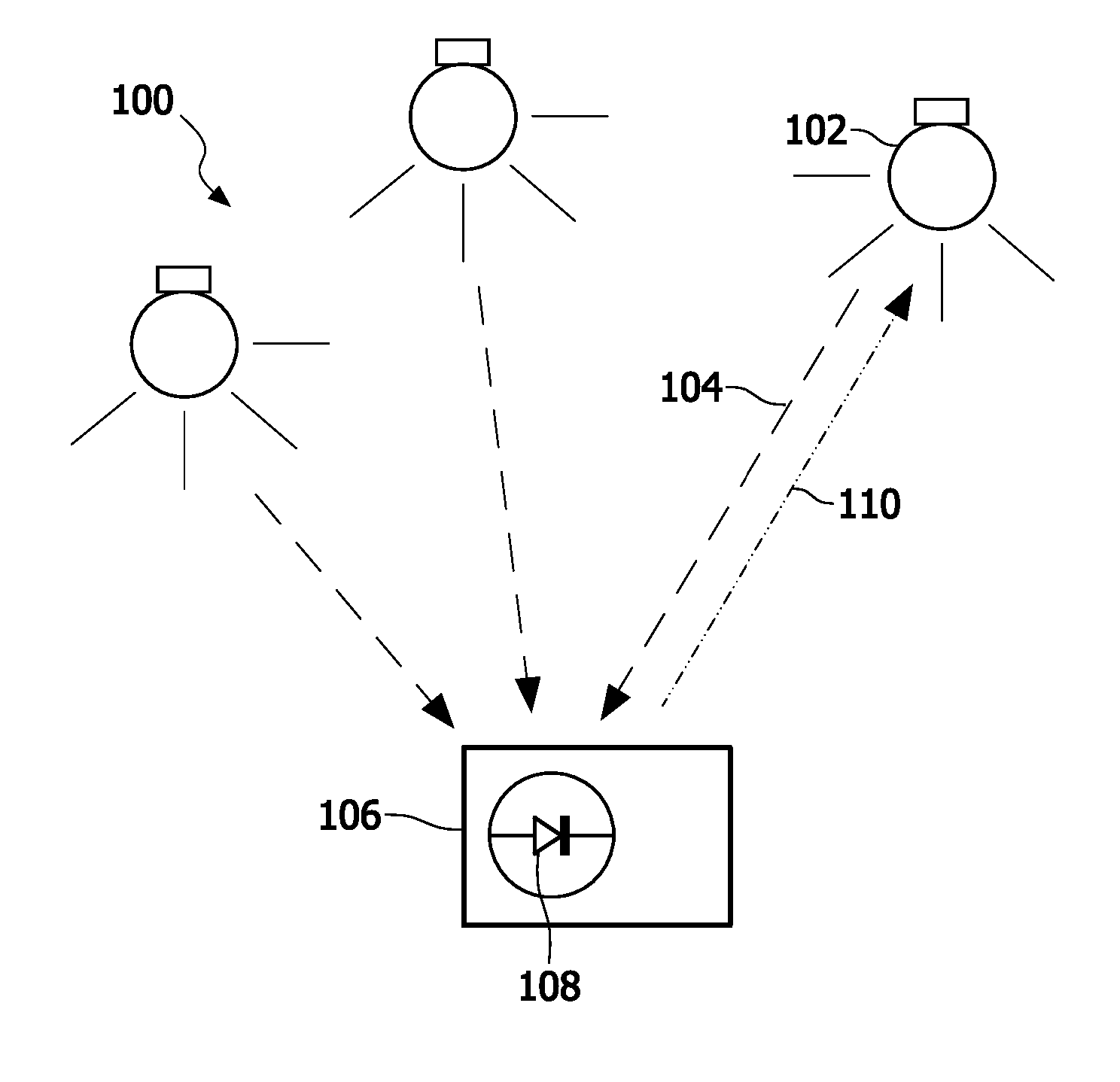
[0044]Operation of a lighting system will now be disclosed with reference to the lighting system 100 of FIG. 1. The lighting system 100 comprises at least one light source, schematically denoted by the reference numeral 102.

[0045]It should be noted that the term “light source” means a device that is used for providing light in a room, for purpose of illuminating objects in the room. Examples of such light providing devices include lighting devices and lumin...


PUM


Abstract

Coded light has been proposed to enable advanced control of light sources and transmit information using light sources. It is based on invisibly embedding of data and identifiers in their light output. Methods, devices and systems configured to efficient assignment of addresses in a coded lighting system, still allowing for unique identification, are proposed. More specifically, the assignment of addresses occurs in two phases, where in the initial phase wide area unique addresses are used, while in the second phase only local area unique addresses are used. Also, methods, devices and systems configured to efficiently distribute a set of addresses over a set of light sources in this second phase, to maximize the performance of the illumination contribution estimation, and positioning, are disclosed.

Description

FIELD OF THE INVENTION[0001]The present invention relates to operating a lighting system. Particularly it relates to methods and devices for operating a lighting system comprising a plurality of light sources each of which is enabled to emit coded light.BACKGROUND OF THE INVENTION[0002]Coded light (CL) has been proposed to enable advanced control of light sources. Coded light is based on embedding of data, inter alia invisible identifiers, in the light output of the light sources. Coded light may thus be defined as the embedding of data and identifiers in the light output of a visible light source, wherein the embedded data and / or identifier perferably do not influence the primary lighting function (i.e. illumination) of the light source. Hence, any modulation of the emitted light pertaining to data and / or identifier should be invisible to humans. This allows for applications such as interactive scene setting, commissioning and re-commissioning of networked lighting systems. Coded l...

Claims


Application Information

Patent Timeline
IPC IPC(8): H05B37/02H05B44/00
CPCH05B37/0245H05B37/0272H05B37/0254H05B47/18H05B47/175H05B47/19H05B47/195H05B47/199H04B10/116
Inventor SCHENK, TIM CORNEEL WILHELMUSYANG, HONGMINGFERI, LORENZORIETMAN, WIJNAND JOHANNESTALSTRA, JOHAN CORNELISLINNARTZ, JOHAN PAUL MARIE GERARD
Owner KONINKLIJKE PHILIPS ELECTRONICS NV
Why Eureka
Try Eureka