Method for Auto Angle Setting of Infrared Sensor Module and Display Device Having the Same Applied Thereto

a technology of infrared sensor and display device, applied in the field of display device, can solve the problems of inability to correct deviation, inability to adjust the angle of infrared sensor, and additional work and time required for the correction of deviation

Active Publication Date: 2012-05-03
LG DISPLAY CO LTD
View PDF2 Cites 7 Cited by
  • Summary
  • Abstract
  • Description
  • Claims
  • Application Information

AI Technical Summary

Benefits of technology

[0017]An object of the present invention is to provide a method for auto angle setting of an infrared sensor module in which an effective angle of view is set automatically every time a di

Problems solved by technology

However, since the infrared sensor in the related art infrared type touch screen is positioned on the outside of the display module, a position of the infrared sensor is liable to deviate from a normal position during transportation or fabrication of the display device, or by shaking in a case of a finished display device.
Thus, if the infrared sensor is deviated, additional work and time is required for correction of the deviation before shipment, and the correction of the deviatio

Method used


Image

  • Method for Auto Angle Setting of Infrared Sensor Module and Display Device Having the Same Applied Thereto
  • Method for Auto Angle Setting of Infrared Sensor Module and Display Device Having the Same Applied Thereto
  • Method for Auto Angle Setting of Infrared Sensor Module and Display Device Having the Same Applied Thereto

Examples


Embodiment Construction

[0055]Reference will now be made in detail to the specific embodiments of the present invention, examples of which are illustrated in the accompanying drawings. Wherever possible, the same reference numbers will be used throughout the drawings to refer to the same or like parts.

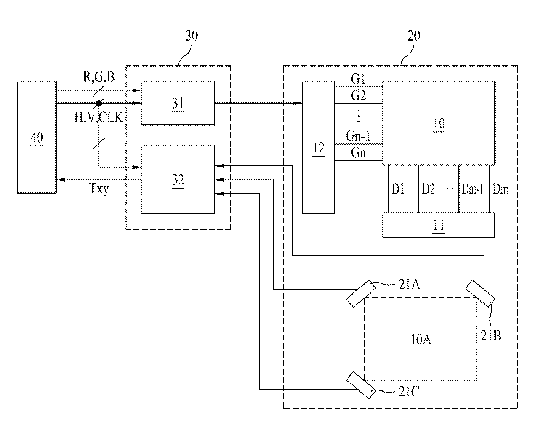
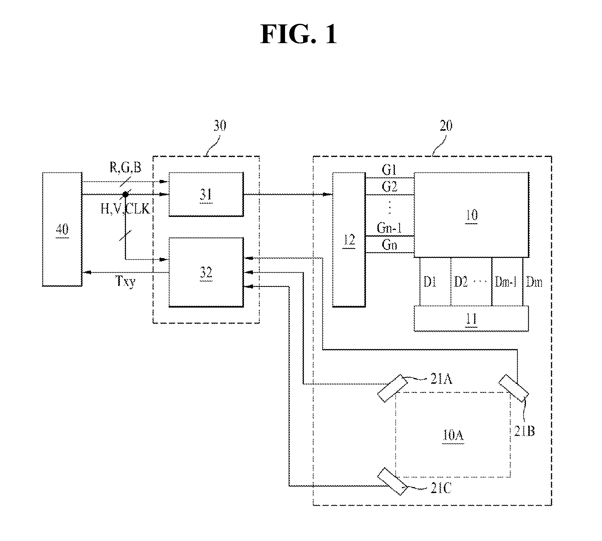
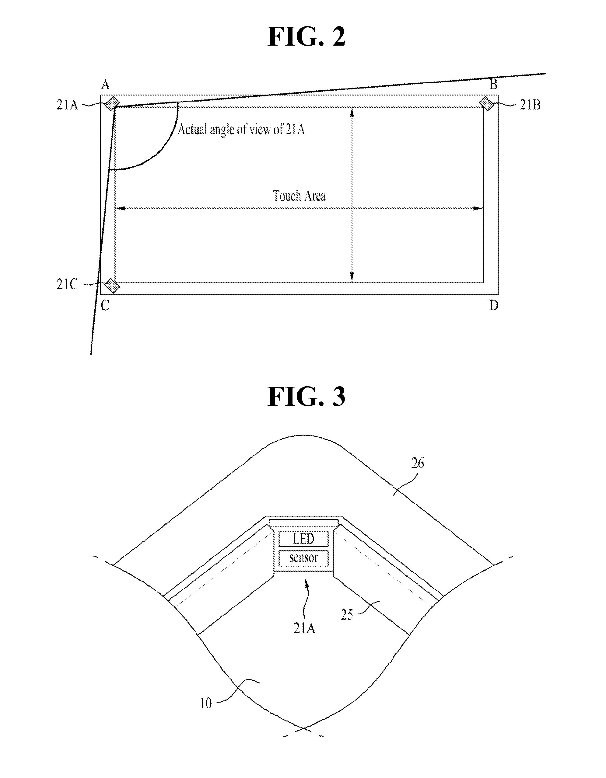
[0056]FIG. 1 illustrates a block diagram of a display device in accordance with a preferred embodiment of the present invention, FIG. 2 illustrates a plan view of a display device in accordance with a preferred embodiment of the present invention, showing an angle of view and a touch region, and FIG. 3 illustrates a perspective view of a corner of the display device in accordance with a preferred embodiment of the present invention, showing a first infrared sensor module mounted thereto.

[0057]Referring to FIGS. 1 to 3, the display device includes a display module 20 having infrared sensor modules 21A˜21C respectively arranged at corners of a display panel which displays a picture, a control board 30 for contr...


PUM


Abstract

The present invention relates to a method for auto angle setting of an infrared sensor module having a light emitting unit and a sensor unit arranged at least two corners of a display panel, includes the steps of selecting a peak detection mode or a slope detection mode; in the peak detection mode, setting a pixel of in the sensor unit which senses a light quantity as a reference point corresponding to a corner other infrared sensor module is arranged at; in the slope detection mode, analyzing the light quantities of a start pixel block and an end pixel block in the sensor unit and setting a pixel which forms a greatest slope as a start point or an end point; and setting an effective angle of view in the sensor unit with reference to the reference point, the start point, and the end point.

Description

CROSS REFERENCE TO RELATED APPLICATION[0001]This application claims the benefit of the Patent Korean Application No. 10˜2010˜0107341, filed on Oct. 29, 2010, which is hereby incorporated by reference as if fully set forth herein.BACKGROUND OF THE DISCLOSURE[0002]1. Field of the Disclosure[0003]The present invention relates to a display device which detects a touch optically, and more particularly to a method for auto angle setting of an infrared sensor module which senses a light and a display device having the same applied thereto.[0004]2. Discussion of the Related Art[0005]In general, a touch screen, one of interface types between a user and an information and communication device which uses various kinds of displays, is an input unit which enables interface with the device by touching a screen with a hand or a pen, personally.[0006]Being a device that can be used by any one only by touching a button displayed on a display device with a finger, handling the touch screen conversati...

Claims


Application Information

Patent Timeline
IPC IPC(8): G06F3/042G01J5/10
CPCG06F3/0418G06F3/0428G06F3/0421G06F2203/04103
Inventor PARK, JAE-HYUNYU, BYUNG-CHUNSONG, SHI-CHEOLCHOI, SUK-WON
Owner LG DISPLAY CO LTD
Why Eureka
Try Eureka