Remote confined-space machining, and positioning and securing arrangement

Inactive Publication Date: 2012-06-07
UNIV OF SHEFFIELD
View PDF11 Cites 6 Cited by
  • Summary
  • Abstract
  • Description
  • Claims
  • Application Information

AI Technical Summary

Benefits of technology

[0057]the electromagnets are gradually energisable to provide resistance and damping of relev

Problems solved by technology

Nevertheless, while this may reduce the need for machining of components, it does not entirely remove it, and it may render what is needed somewhat more complex.
Even multiple component parts often require machining in hard-to-reach places after their initial construction.
Next, although, ultimately, precise positioning is perfectly possible, it is difficult to move a remote arm, if it is long and flexible, without small movements being exaggerated at the tool head by the flexibility of the arm and the distance of the tool head from the stable base of the robot.
However, in hard-to-reach places, providing such reaction member is often problematic.
One approach is to employ a rigid mounting for the machining tool, but in confined spaces, maneuvering

Method used


Image

  • Remote confined-space machining, and positioning and securing arrangement
  • Remote confined-space machining, and positioning and securing arrangement
  • Remote confined-space machining, and positioning and securing arrangement

Examples


Embodiment Construction

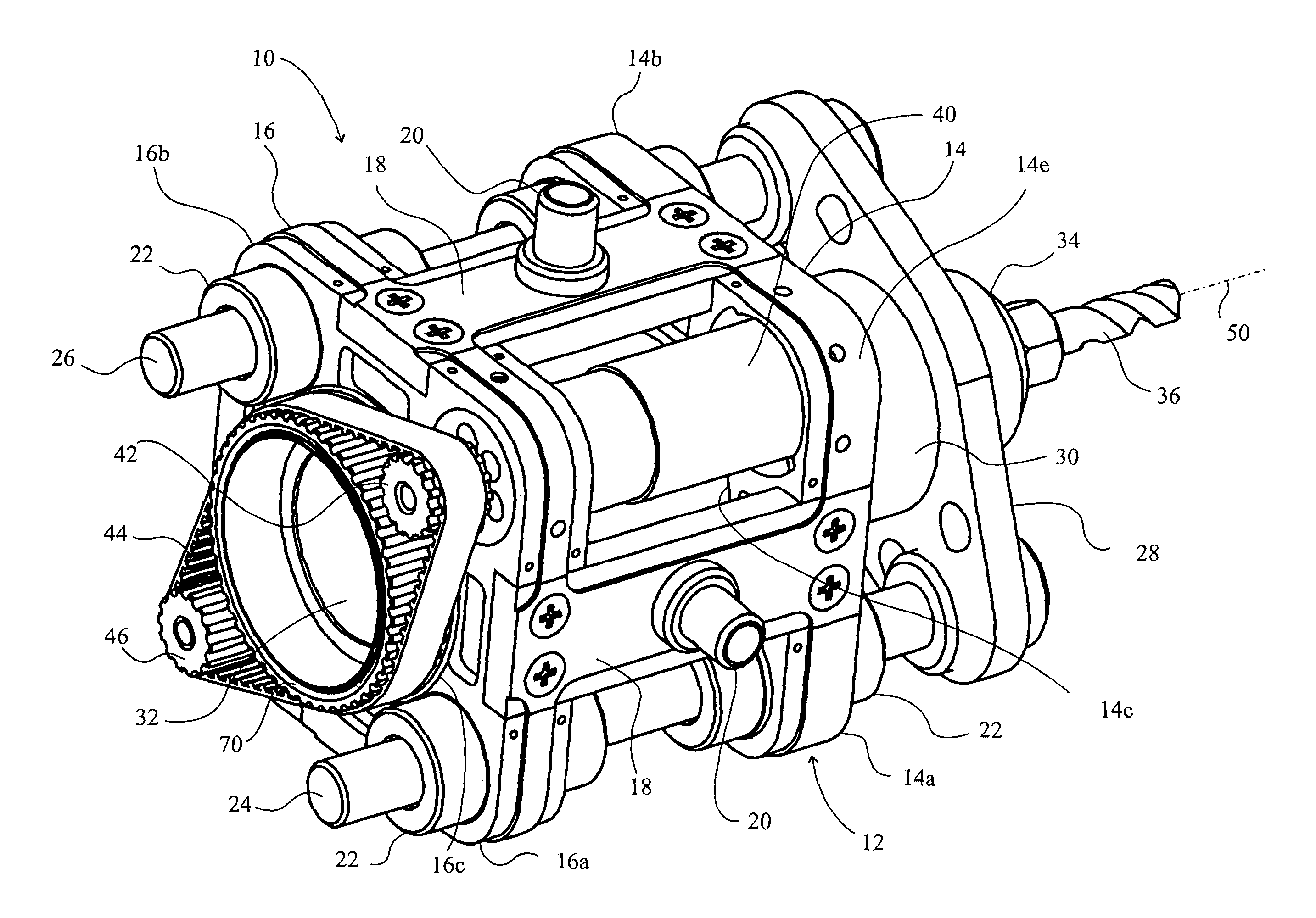
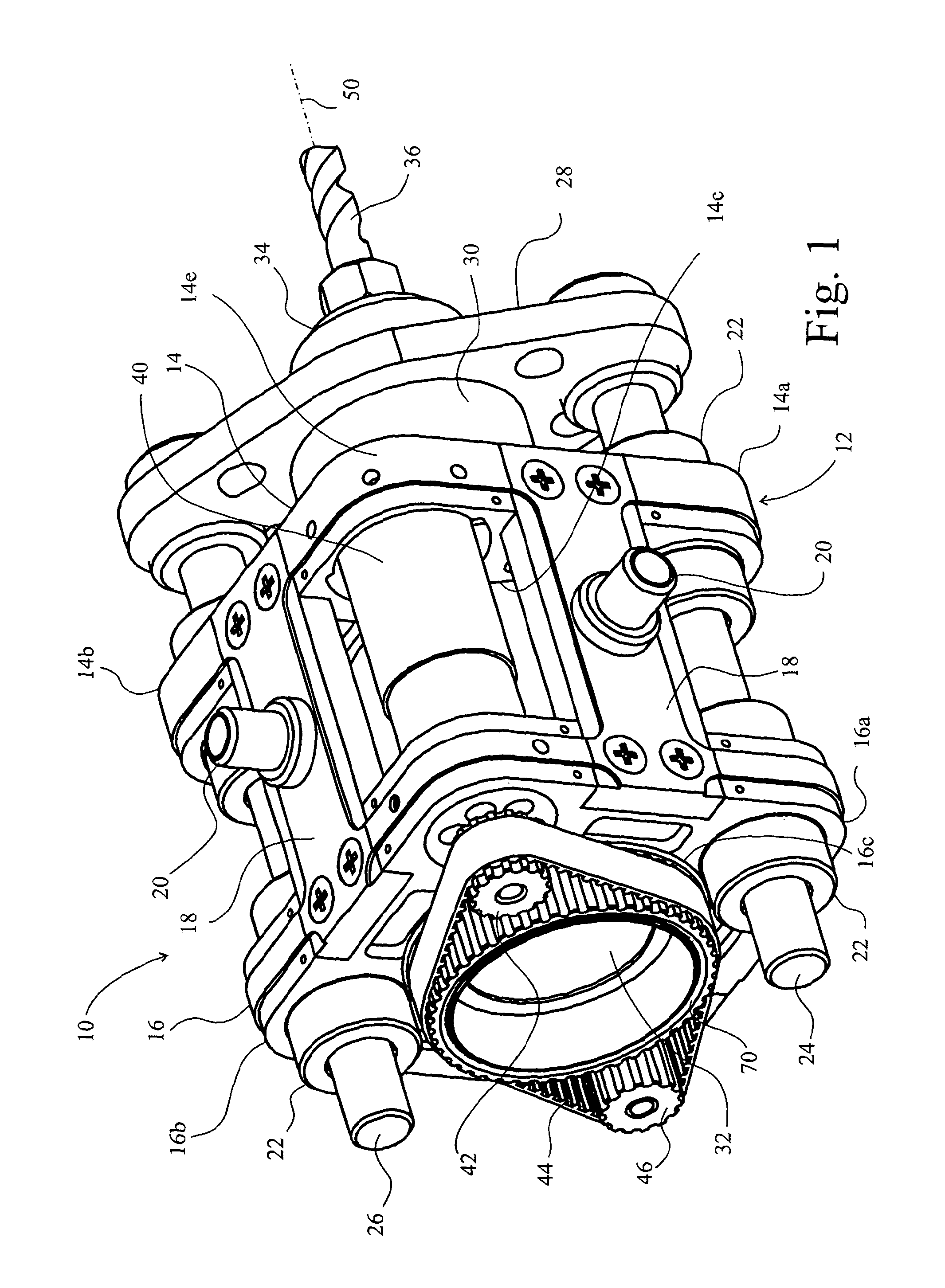
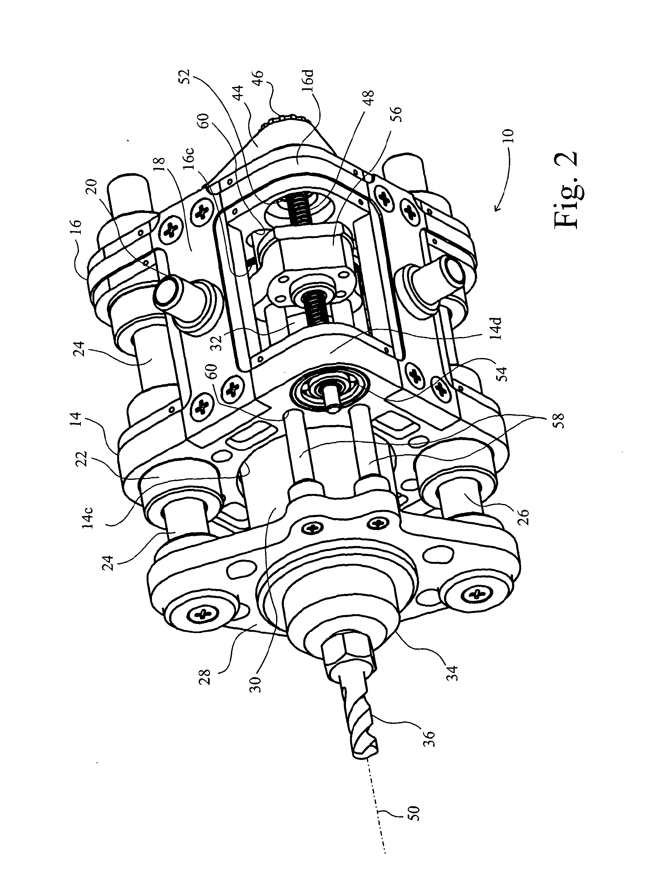
[0088]A drilling tool 10 comprises a frame 12 that has a fore plate 14 and an aft plate 16 connected together by limbs 18. The plates 14,16 are rounded squares, so that there are four limbs 18. At least one of the limbs incorporates a mounting flange 20 for connection to a robot arm (not shown).

[0089]Opposing corners 14a,b of the fore plate 14 and 16a,b of the aft plate 16 incorporate sleeve bearings 22 through which a pair of pillars 24,26 slide. The pillars 24,26 are fixed on a yoke 28 on which is also mounted a tool motor 30. The tool motor 30 has a body 32 that is substantially cylindrical and drives an armature (not shown) about a longitudinal axis 50 of the tool 10. A chuck 34 receives a drill bit 36 to be driven by the motor 30 for drilling holes in a workpiece (not shown).

[0090]In drilling holes, it is of course necessary to advance the drill bit 36 in the direction of the hole it is drilling, which is in the direction of axis 50 in FIG. 1. It is of course feasible that a ro...


PUM

PropertyMeasurementUnit
Speedaaaaaaaaaa

Abstract

A machining tool comprises a frame mounting an extendable yoke slidable with respect to the frame in a first direction through one or more mounting pillars. A tool motor is mounted on the yoke. A drive mechanism for the yoke is also mounted in the frame, with a drive motor to drive the yoke drive mechanism. A belt is between pulleys on the drive motor and mechanism to transmit drive between them. A rotatable sleeve is around the tool motor and on which sleeve the belt engages on opposite sides of the tool motor, whereby the tool motor can extend between the drive motor and mechanism, thereby resulting in a compact arrangement of the tool.

Description

[0001]This invention relates to a system for positioning and holding a machine for working in a confined space at a distance from a support base. It relates to means rendering the machine compact, but also secure in a correct position. In another aspect, it relates to mounting structure being an arrangement of a mechanism for permitting adjustment of the position of any device laterally with respect to a substrate to which the device is connected.BACKGROUND[0002]It is often required to machine a component somewhat remotely. This is becoming more common in advanced manufacturing, particularly in the aeronautic industries where the tendency is towards larger and larger monolithic components. Large monolithic components have fewer joints that can be a source of weakness. Nevertheless, while this may reduce the need for machining of components, it does not entirely remove it, and it may render what is needed somewhat more complex. Even multiple component parts often require machining in...

Claims


Application Information

Patent Timeline
IPC IPC(8): B23Q5/22B23Q1/48
CPCB23Q1/4876B23Q5/326Y10T403/32467Y10T408/675Y10T409/309352Y10T408/56245B23Q1/34B23Q5/04B23Q5/225B23Q5/32B23K20/1245B23Q5/402H02K7/06
Inventor NICHOLSON, GARTH MARTYN JOHN
Owner UNIV OF SHEFFIELD
Why Eureka
Try Eureka