System and method for forming an image on a substrate

a technology of system and substrate, applied in electrographic process, coating, instruments, etc., can solve the problems of not being suitable for high-speed printing processes, not widely known for optically variable devices intended to be noticed, and not providing a way in which flakes in a binder within adjacent regions can be selectively cured

a technology of system and substrate, applied in electrographic process, coating, instruments, etc., can solve the problems of not being suitable for high-speed printing processes, not widely known for optically variable devices intended to be noticed, and not providing a way in which flakes in a binder within adjacent regions can be selectively cured

US20120162344A1Active Publication Date: 2012-06-28VIAVI SOLUTIONS INC

Image

  • System and method for forming an image on a substrate
  • System and method for forming an image on a substrate
  • System and method for forming an image on a substrate

Examples


Embodiment Construction

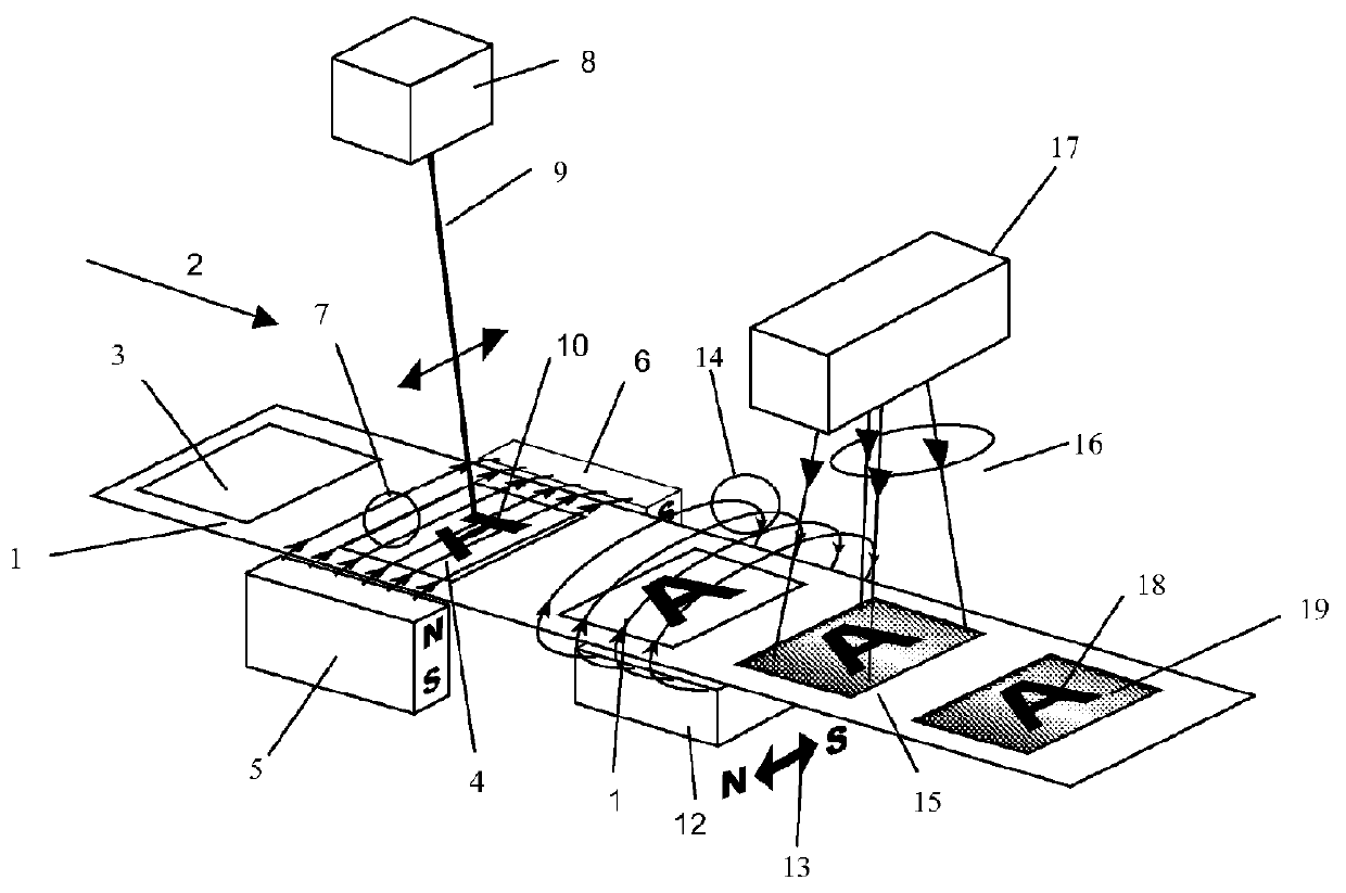
[0041]This invention provides a high-speed system and method for applying field-alignable flakes in ink or paint to a substrate in a plurality of regions and for aligning flakes within a region, and in-situ, while the flakes are aligned within an applied field such as a magnetic field, freezing those flakes in their magnetically aligned position by writing an image in the wet magnetic ink with an ultra-violet (UV) laser beam. Ink that is not exposed to the UV beam is not cured and flakes within this ink are not fixed in their aligned position and only flakes that have been written or cured in their clear or tinted ink or paint carrier with the UV beam are cured and fixed in their aligned position as UV curing binder solidifies. This system and method provides selective curing of locations within the wet ink as the substrate passes through the magnetic field at speeds of 25 ft / min and even up to speeds of 400 ft / min or greater.

[0042]There are several aspects, which make this system a...


PUM


Abstract

A scanning laser having a wavelength compatible with a coating binder so as to cure it as the laser scans and irradiates the coating on a moving web. A system and method for curing flakes by providing a scanning laser which scans across a moving coated substrate in a magnetic field allows images to be formed as magnetically aligned flakes are cured into a fixed position. The images have regions of cured aligned flakes. The scanning laser cures the magnetically aligned flakes within it region it irradiates. Alternatively an array of lasers can be used wherein individual lasers can be switched on and off to fix irradiated coating as a moving web is moved at a high speed.

Description

CROSS-REFERENCE TO RELATED APPLICATIONS[0001]This application claims priority from U.S. Provisional Patent Application No. 61 / 427,319 filed Dec. 27, 2010, which is incorporated herein by reference for all purposes.FIELD OF THE INVENTION[0002]This invention relates generally to using a beam of light to selectively cure regions of a substrate coated with magnetically aligned pigment flakes within a binder.BACKGROUND OF THE INVENTION[0003]Optically variable devices are used in a wide variety of applications, both decorative and utilitarian. These devices can be made in variety of ways to achieve a variety of effects. Examples of optically variable devices include the holograms imprinted on credit cards and authentic software documentation, color-shifting images printed on banknotes, and enhancing the surface appearance of items such as motorcycle helmets and wheel covers.[0004]Optically variable devices can be made as film or foil that is pressed, stamped, glued, or otherwise attached ...

Claims


Application Information

Patent Timeline
28 Jun 2012
Publication
US20120162344A1
IPC
B41J2/475; B41J2/435; B41J2/455
CPC
B05D3/207; B41M3/14; B05C9/12; G03G19/00; G03G2215/0013; G03G15/2007
Inventors
RAKSHA, VLADIMIR P.; HRUSKA, CURTIS R.