Pneumatic tire

A technology of pneumatic tires and tires, which is applied to tire parts, tire edges, tire sidewalls, etc., can solve problems such as air peeling, and achieve the effect of preventing peeling and preventing peeling.

Active Publication Date: 2010-12-01
SUMITOMO RUBBER IND LTD
View PDF6 Cites 10 Cited by
  • Summary
  • Abstract
  • Description
  • Claims
  • Application Information

AI Technical Summary

Problems solved by technology

[0009] However, in the technique of the above-mentioned Patent Document 1, air may still be trapped between the convex portion and the concave portion of the mold to cause peeling.

Method used


Image

  • Pneumatic tire
  • Pneumatic tire
  • Pneumatic tire

Examples


Embodiment Construction

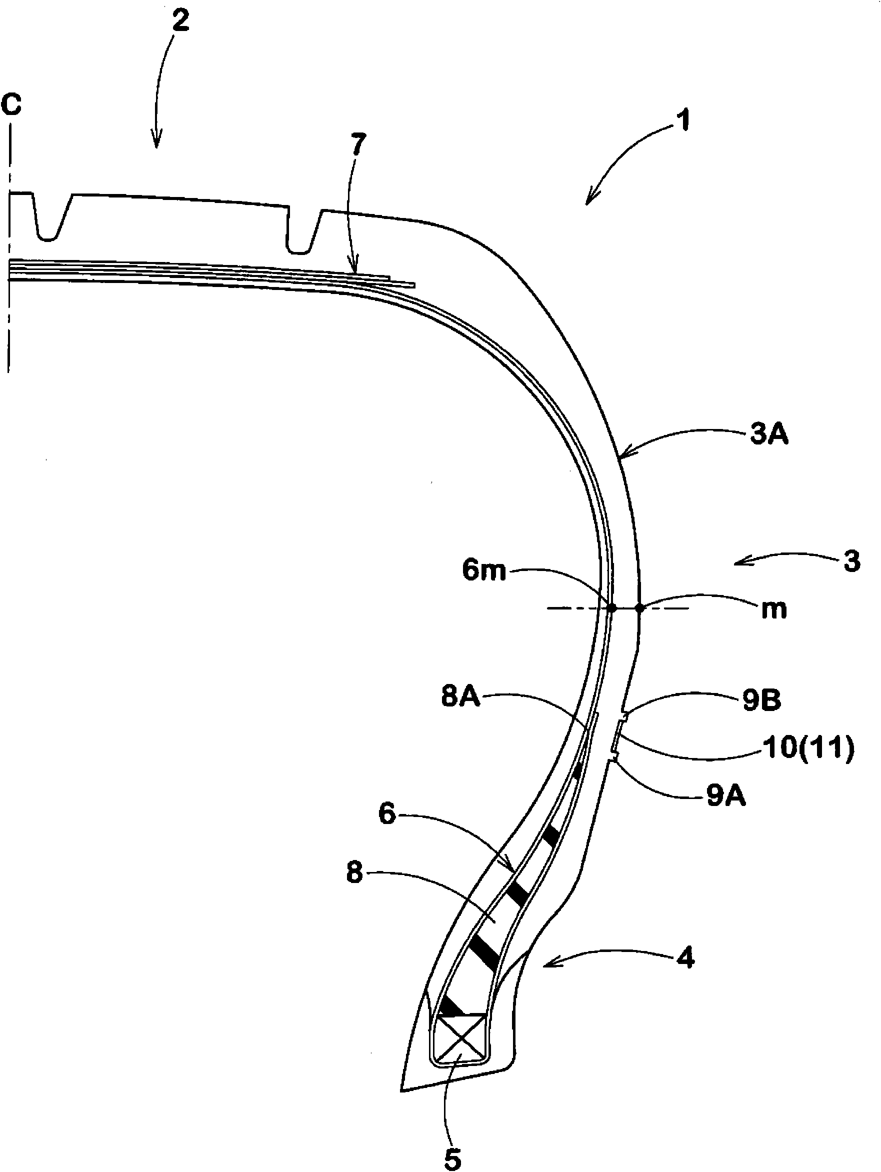
[0031] Hereinafter, one embodiment of the present invention will be described based on the drawings.

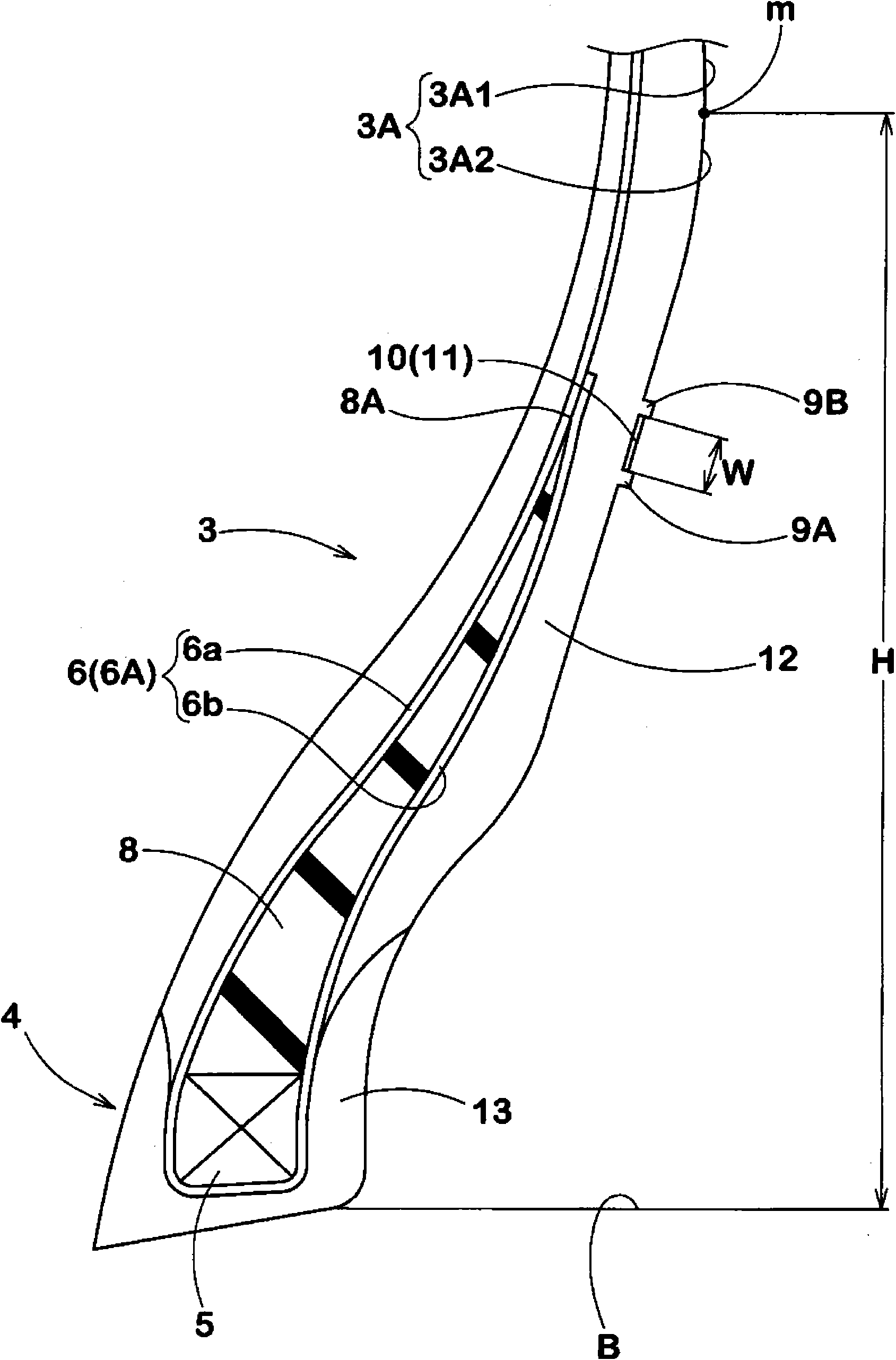
[0032] Such as figure 1 and figure 2 As shown, the pneumatic tire 1 of the present embodiment has: a tread portion 2; a pair of sidewall portions 3 extending radially inward from both ends of the tread portion; The bead portion 4 is a car tire vulcanized and molded using a vulcanization mold in this example.

[0033] here, figure 1 It shows the normal state in which the pneumatic tire 1 of the present embodiment is assembled to a normal rim (not shown), filled with normal internal pressure, and unloaded. In addition, unless otherwise specified, the dimensions of each part of the tire are values ​​in the normal state.

[0034] In addition, the above-mentioned "regular rim" refers to the rim specified for each tire in the specification system including the specification on which the tire is based. For example, in the case of JATMA, it is "standard rim", and in the case o...


PUM


Abstract

The invention provides a pneumatic tire in which bareness of rubber on the tire outer surface is effectively prevented. The outer surface of the tire is provided in its region radially inside a maximum width position of the carcass with vent lines (9) extending in a tire circumferential direction, wherein the vent lines (9) include a radially inner first vent line (9A) and a radially outer second vent line (9B). The area between the first vent line (9A) and second vent line (9B) is formed as a serrated area (11) comprising a plurality of circumferentially spaced small ribs (10) extending from the first vent line (9A) to the second vent line (9B). The serrated area (11) has deepest parts and shallowest parts. The shallowest parts are located inside the ridge of each of the vent lines, and the deepest parts are located at the same level as or outside a virtual tire outer surface.

Description

technical field [0001] The present invention relates to a pneumatic tire capable of suppressing spalling on the outer surface of the tire. Background technique [0002] Pneumatic radial tires are generally manufactured by vulcanizing and molding a green tire by integrating an annular tread member including a belt and tread rubber with an annular tire main body including a carcass using a mold. into. During vulcanization molding, it is desirable that the raw tires come into contact with the molding surface of the mold simultaneously or sequentially from the radially inner side. [0003] In practice, however, slow contact tends to occur in the region of the green tire that is closer in the tire radial direction than the tire maximum width position, especially in the vicinity of the relatively rigid bead portion. Therefore, air is enclosed between the outer surface of the bead portion and the molding surface of the mold (hereinafter, the air enclosed in this way may be referr...

Claims


Application Information

Patent Timeline
Patent Type & Authority Applications(China)
IPC IPC(8): B60C13/00B60C15/00
CPCB60C2019/008B60C13/02B60C13/001
Inventor 向井友幸
Owner SUMITOMO RUBBER IND LTD
Why Eureka
Try Eureka