Arrangement for connecting a drawer frame to the bottom of a drawer

a drawer frame and drawer bottom technology, applied in the direction of drawers, furniture parts, domestic applications, etc., can solve the problems of weakened support legs in loading and resistance to deformation, and achieve the effect of slowing down the retraction movement of pawl components, simple installation and quick

Inactive Publication Date: 2008-11-25
THOMSON LICENSING SA +1
View PDF24 Cites 10 Cited by
  • Summary
  • Abstract
  • Description
  • Claims
  • Application Information

AI Technical Summary

Benefits of technology

[0016]A damping device which slows down the retraction movement of the pawl component after it has been triggered by the catch is then advantageously provided in the housing of the automatic retraction device, and the damping device can be provided with a damper which is known per se and has a fluid or gaseous damping medium.
[0017]The housing of the automatic retraction device is advantageously latched with the supporting leg of the associated connector component, so that the automatic retraction device can be installed simply and quickly as required—even at a later stage.
[0018]The housing of the automatic retraction device can—depending upon the length of the retraction path as predetermined by the design—be markedly longer than the width of the supporting leg of the connector component. If this housing projects significantly over the supporting leg in the horizontal direction it is advantageous if the housing is additionally connected to the drawer frame in its region which projects over the supporting leg.

Problems solved by technology

Due to the slotting of the supporting leg which passes through to the free edge in order to form the fixing claws, the supporting leg is weakened in its loading and in its resistance to deformation.

Method used


Image

  • Arrangement for connecting a drawer frame to the bottom of a drawer
  • Arrangement for connecting a drawer frame to the bottom of a drawer
  • Arrangement for connecting a drawer frame to the bottom of a drawer

Examples


Embodiment Construction

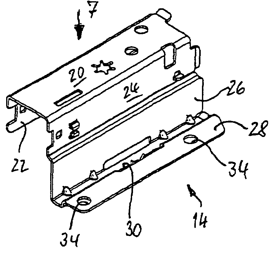
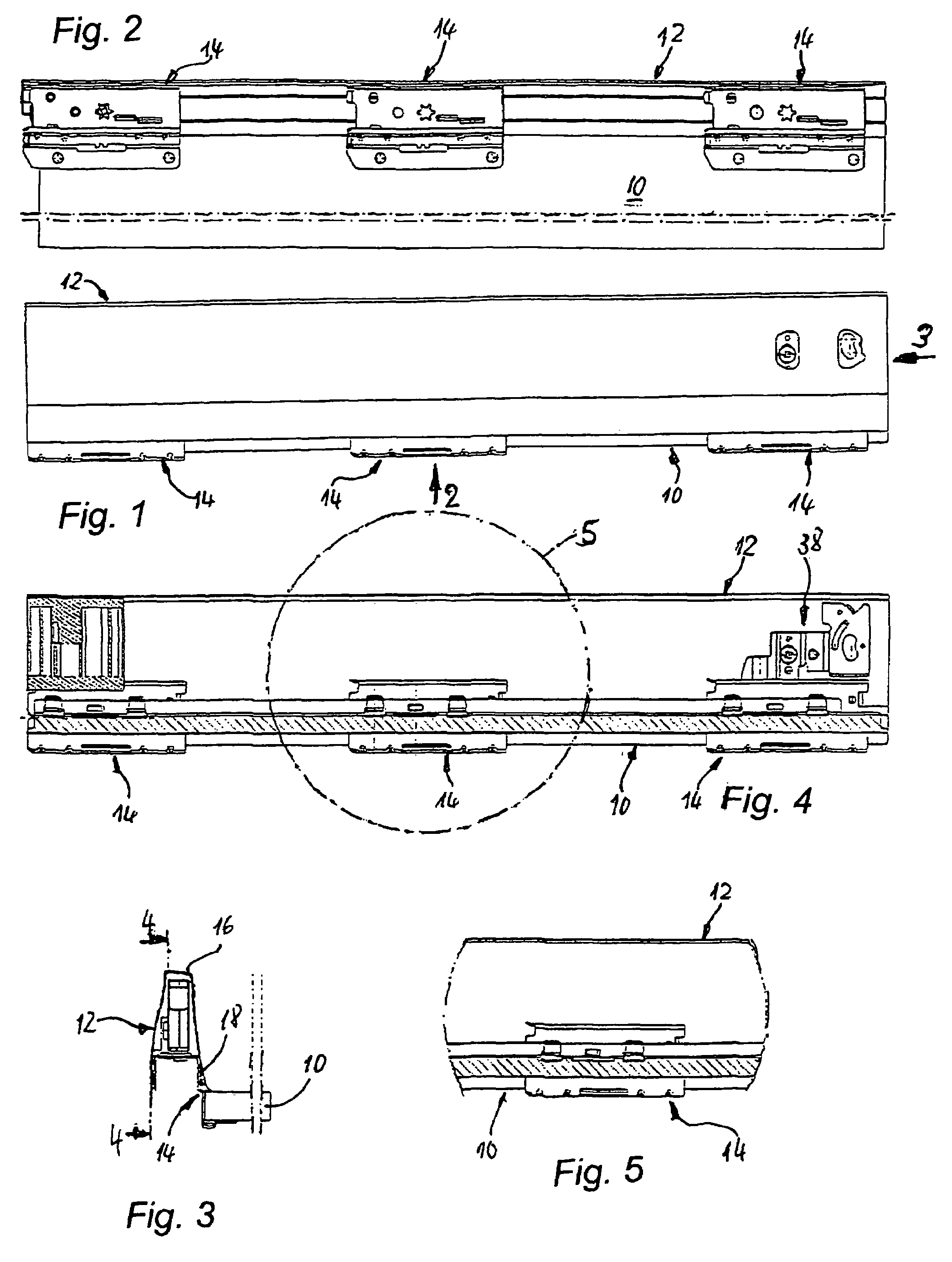
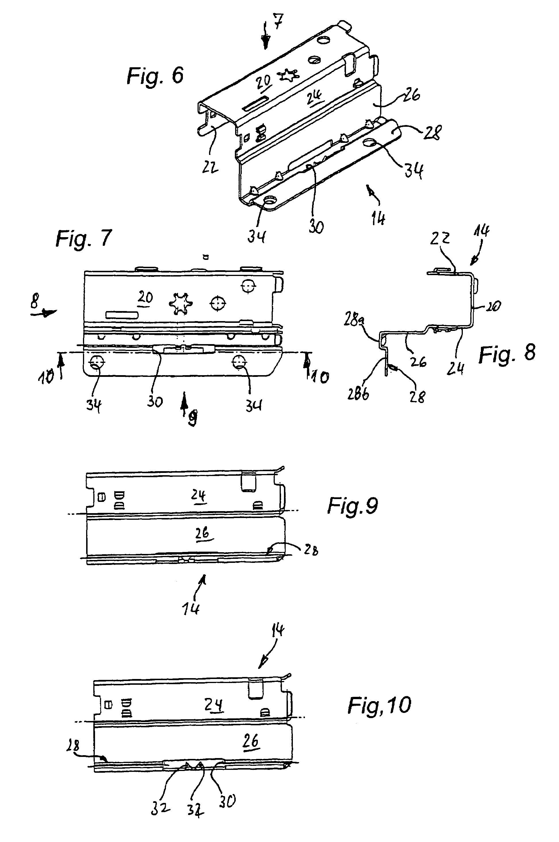
[0032]FIGS. 1 to 5 show the connection of one of the lateral edges of a drawer bottom 10 to a drawer frame 12 which forms a side wall of a drawer by means of—in the illustrated case three—connector components 14. The special configuration of the connector components is described below in connection with FIGS. 6 to 10 in which a connector component 14 is shown separately.

[0033]In the illustrated case the drawer frame 12 is formed by a hollow chamber profile which, corresponding to the previously mentioned hollow chamber profile according to DE 39 34 419 C2 is constituted by two part-profiles 16, 18 bent out of sheet metal. The connector components 14 which are likewise produced from sheet metal with a greater material thickness in a punching and pressing operation are inserted into the underside of the drawer frame which is open like a channel formed by the lower part-profile 18, whereby the region of the connector components 14 lying within the channel-like opening is constructed in...


PUM


Abstract

Arrangement for connecting a drawer frame (12) formed by a metal hallow chamber profile to the facing lateral edge of the associated plate-shaped drawer bottom (10), in which at least in part-regions of its lower end region opposite the end face of the edge of the drawer bottom (10) the drawer frame (12) has in each case a strip-shaped vertical contact web (26) for the lateral end face of the drawer bottom (10), and a supporting leg (28) which engages under the drawer bottom in the proper connection position is bent away from the lower end of the contact web. The supporting leg has integrally projecting from it fixing claws (32) which are pointed or sharpened at their free ends, project over the support surface of the supporting leg (28) and can be pressed into the material of a drawer bottom which is to be fixed. Each supporting leg (28) has at least one elongate punched-out slot (30) which is closed all round in its region between the strip-shaped contact web (26) and its free edge. The fixing claws (32) are attached integrally to one of the edges of the punched-out slot (30) and are extensions formed out of the material of the supporting leg (28) itself which are bent round substantially at right angles in the direction of the drawer bottom (10).

Description

[0001]This is an application filed under 35 USC 371 of PCT / EP03 / 06349.BACKGROUND OF THE INVENTION [0002]The invention relates to an arrangement for connecting a drawer frame formed by a metal hollow chamber profile to the facing lateral edge of the associated plate-shaped drawer bottom, in which at least in part-regions of its lower end region opposite the end face of the edge of the drawer bottom the drawer frame has in each case a strip-shaped vertical contact web for the lateral end face of the drawer bottom, and a supporting leg which engages under the drawer base in the proper connection position is bent away from the lower end of the contact web and has integrally projecting from it fixing claws which are pointed or sharpened at their free ends, project over the support surface of the supporting leg and can be pressed into the material of a drawer bottom which is to be fixed.[0003]In recent times, at least in the case of pieces of high-quality furniture, metal hollow chamber p...

Claims


Application Information

Patent Timeline
Patent Type & Authority Patents(United States)
IPC IPC(8): A47B88/00A47B88/04
CPCA47B88/0422A47B88/047A47B2210/094A47B88/427A47B88/467A47B88/941A47B2210/095
Inventor NACHBAUR, JURGENGRABHER, GUNTER
Owner THOMSON LICENSING SA
Why Eureka
Try Eureka