

Method and system for optically coupling a laser with a transducer in an energy assisted magnetic recording disk drive
a technology of energy assisted magnetic recording and laser, which is applied in the direction of recording information storage, mounting head within the housing, instruments, etc., can solve the problems of difficult alignment of laser diodes with eamr transducers, adverse effects on performance, and inability to manufacture conventional eamr disk drives at reasonable cost and sufficient optical efficiency
- Summary
- Abstract
- Description
- Claims
- Application Information
AI Technical Summary
Problems solved by technology
Method used
Image

Examples
Embodiment Construction
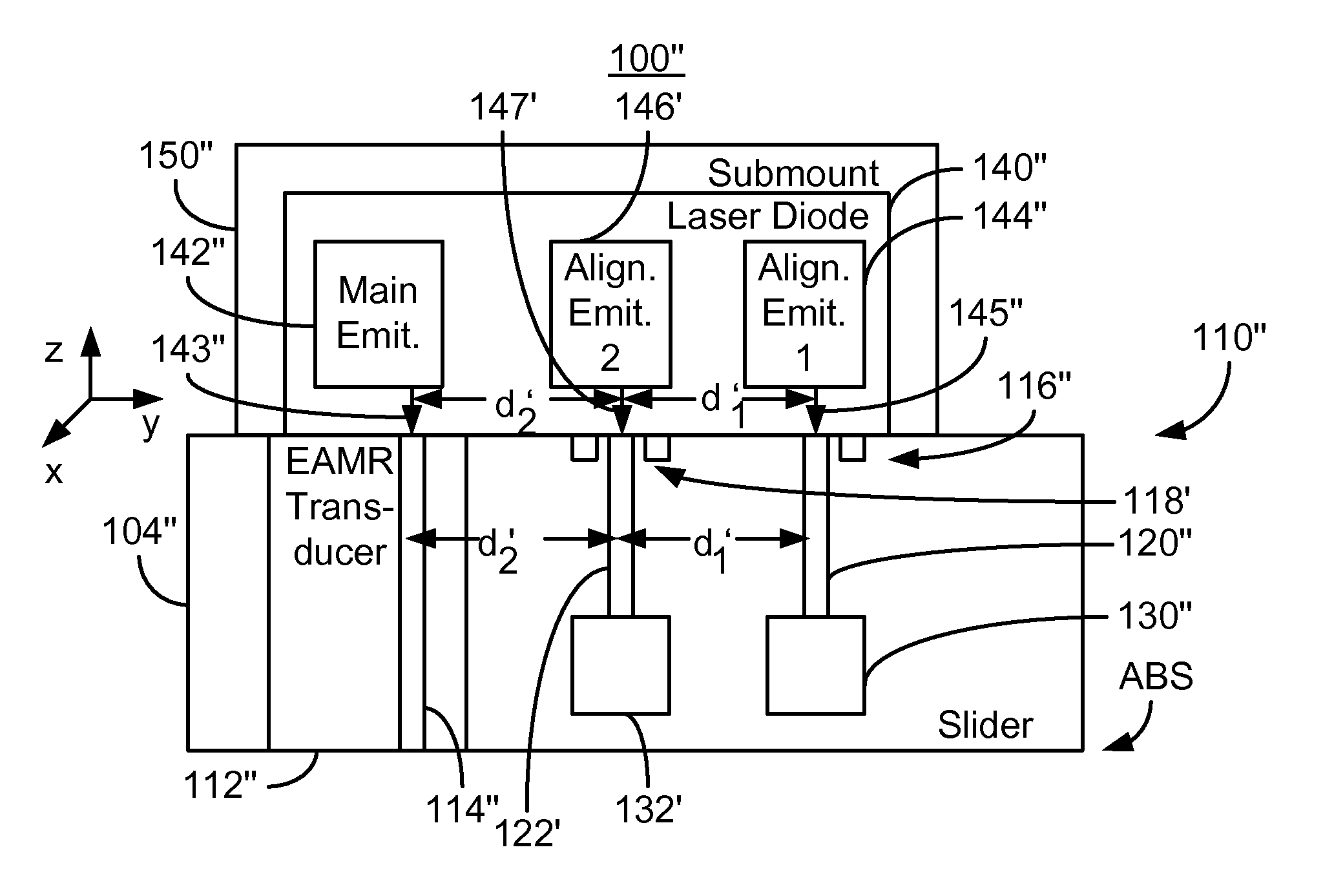
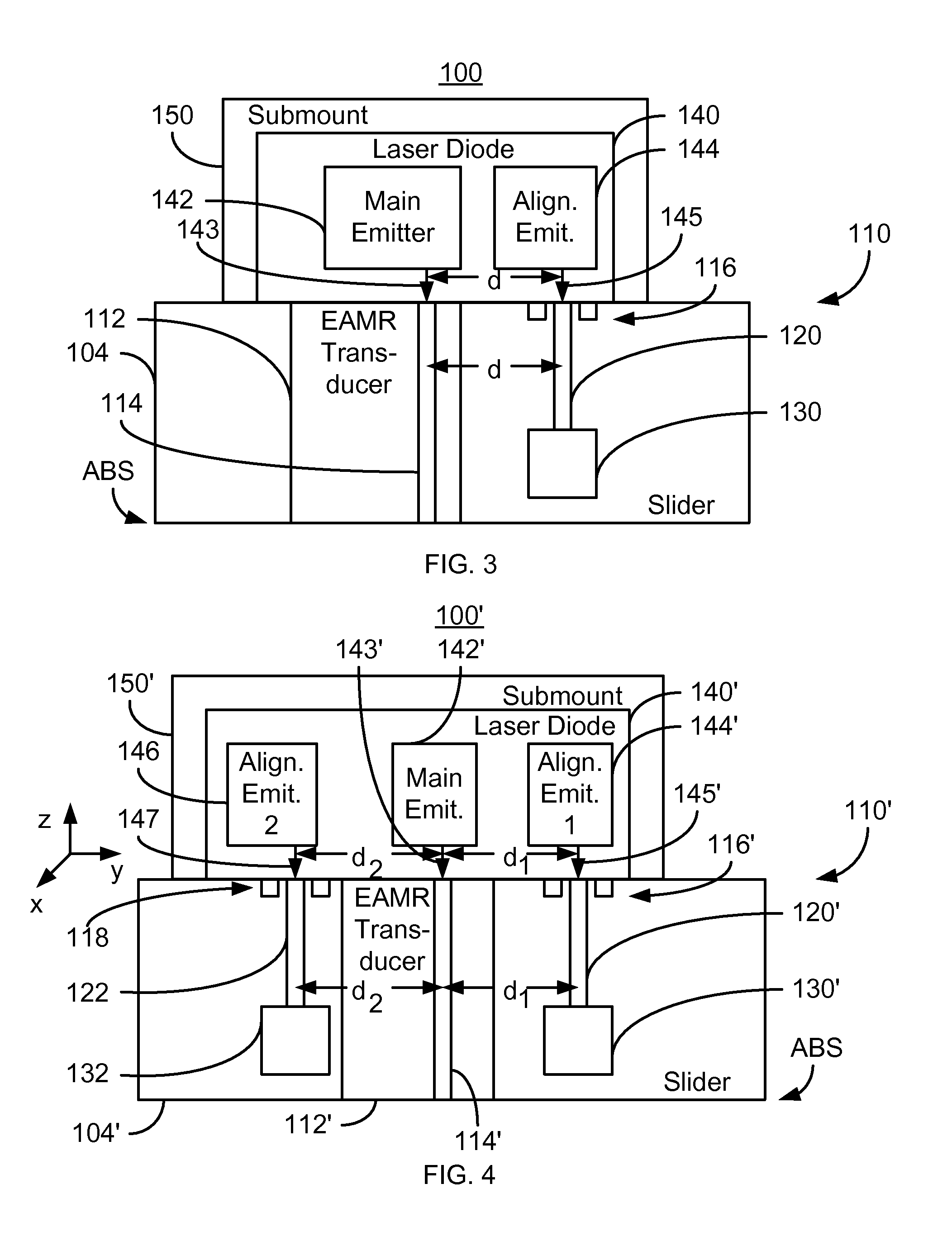
[0016]FIG. 3 is a diagram depicting a portion of an EAMR disk drive 100. For clarity, FIG. 3 is not to scale. For simplicity not all portions of the EAMR disk drive 100 are shown. In addition, although the disk drive 100 is depicted in the context of particular components other and / or different components may be used. In addition, although single components, such as lasers, are shown, multiple components may be used in other embodiments. Further, the arrangement of components may vary in different embodiments.
[0017]The EAMR disk drive 100 includes media (not shown) and an EAMR head 110. The EAMR head 110 includes a slider 104, EAMR transducer 112, alignment waveguide 120, optional output device 130, and laser 140 that is optically coupled with the EAMR transducer 112. In the embodiment shown, the laser 140 is a laser diode that is coupled to the submount 150. Although shown as coupled with the back side of the slider 104, the laser 140 may be located elsewhere. The laser 140 is a mu...
PUM
| Property | Measurement | Unit |
|---|---|---|
| energy | aaaaa | aaaaa |
| external energy | aaaaa | aaaaa |
| optical efficiency | aaaaa | aaaaa |
Abstract
Description
Claims
Application Information