Electrical System Devices, Indicia-Bearing Bodies, and Kits Including Same

Inactive Publication Date: 2012-07-19
EKINS WILLIAM JAMES
View PDF8 Cites 4 Cited by
  • Summary
  • Abstract
  • Description
  • Claims
  • Application Information

AI Technical Summary

Benefits of technology

[0021]The fourth and fifth retaining surfaces may be positioned to cause the first, second, and thi

Problems solved by technology

However, such a switch cover plate assembly disadvantageously requires inserting and removing the label covers into and from the mounting slots, which may be time-consuming and difficult.
If a plurality of such faceplates cover respective such electrical system devices mounted to a wall, and are later removed when the wall is painted, for example, then the faceplates may subsequently be replaced on different such electrical system devices, in which case information on labels under the label covers of the faceplates may become associated with the wrong electrical system devices.
Associating such information with a wrong electrical system device may disadvantageously lead to misuse of the electrical system device, or may disadvantageously cause misidentification of a circuit associated with the electrical system device, for example.
However, in some circumstances, such adhesives may fail, which may disadvantageously lead to loss of information associated with the electrical system device.
Further, such adhesives may be difficult to remove, and therefore changing or removing information associated with the electrical system device may disadvantageously be time-consuming and challenging, and inability to remove adhesives may disadvantageously result in unsightly remains of unwanted labels, for example.

Method used


Image

  • Electrical System Devices, Indicia-Bearing Bodies, and Kits Including Same
  • Electrical System Devices, Indicia-Bearing Bodies, and Kits Including Same
  • Electrical System Devices, Indicia-Bearing Bodies, and Kits Including Same

Examples


Embodiment Construction

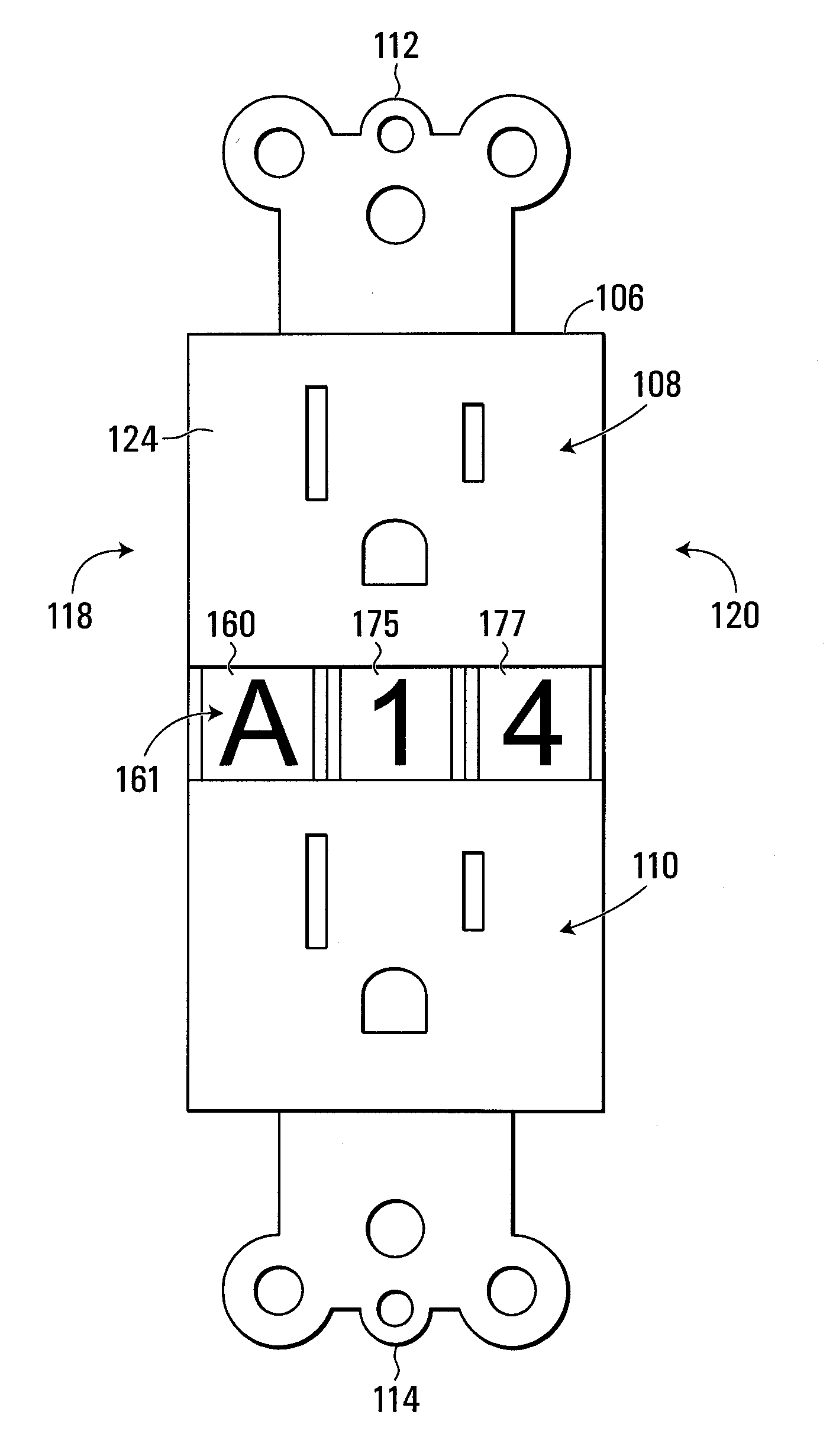
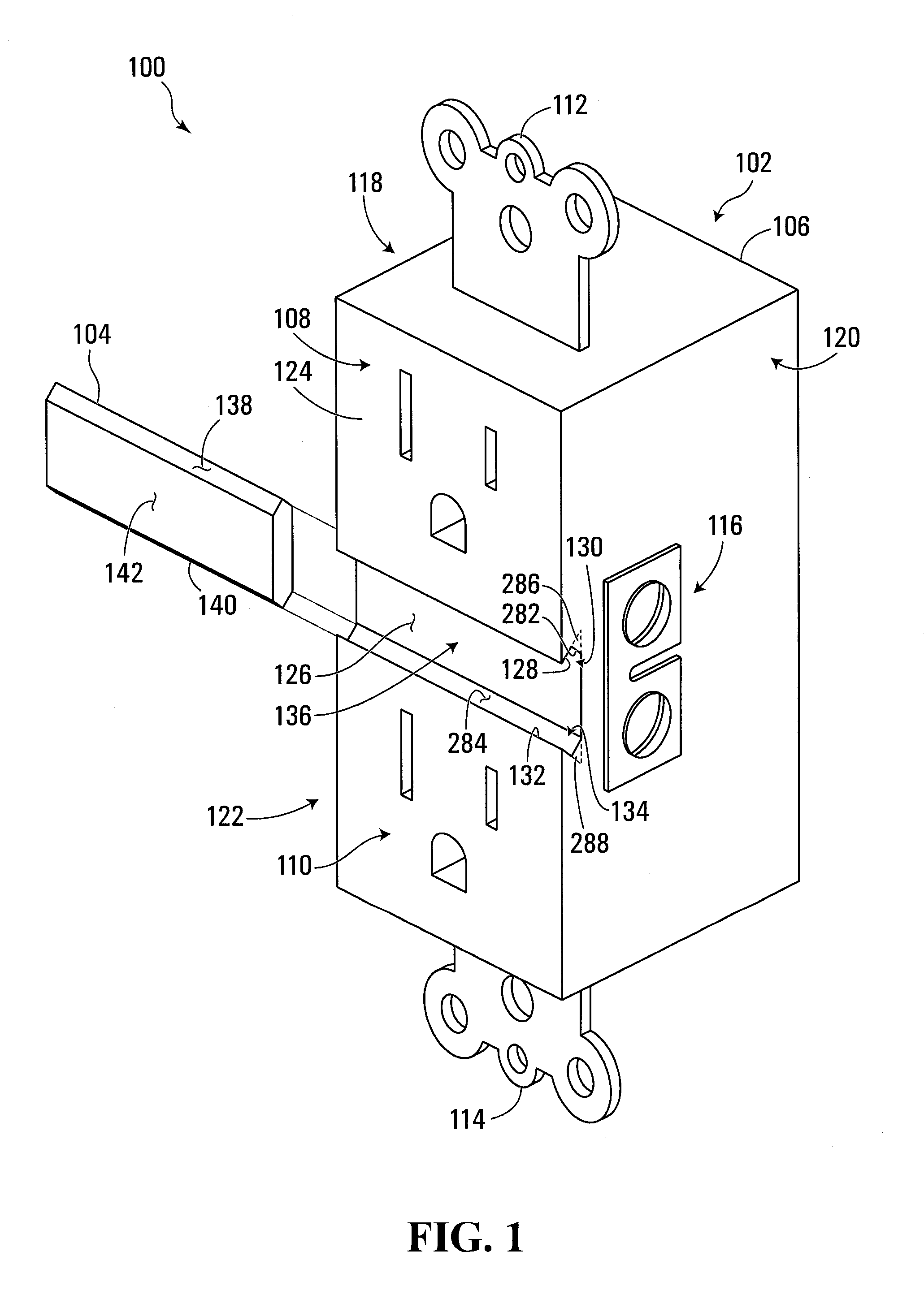
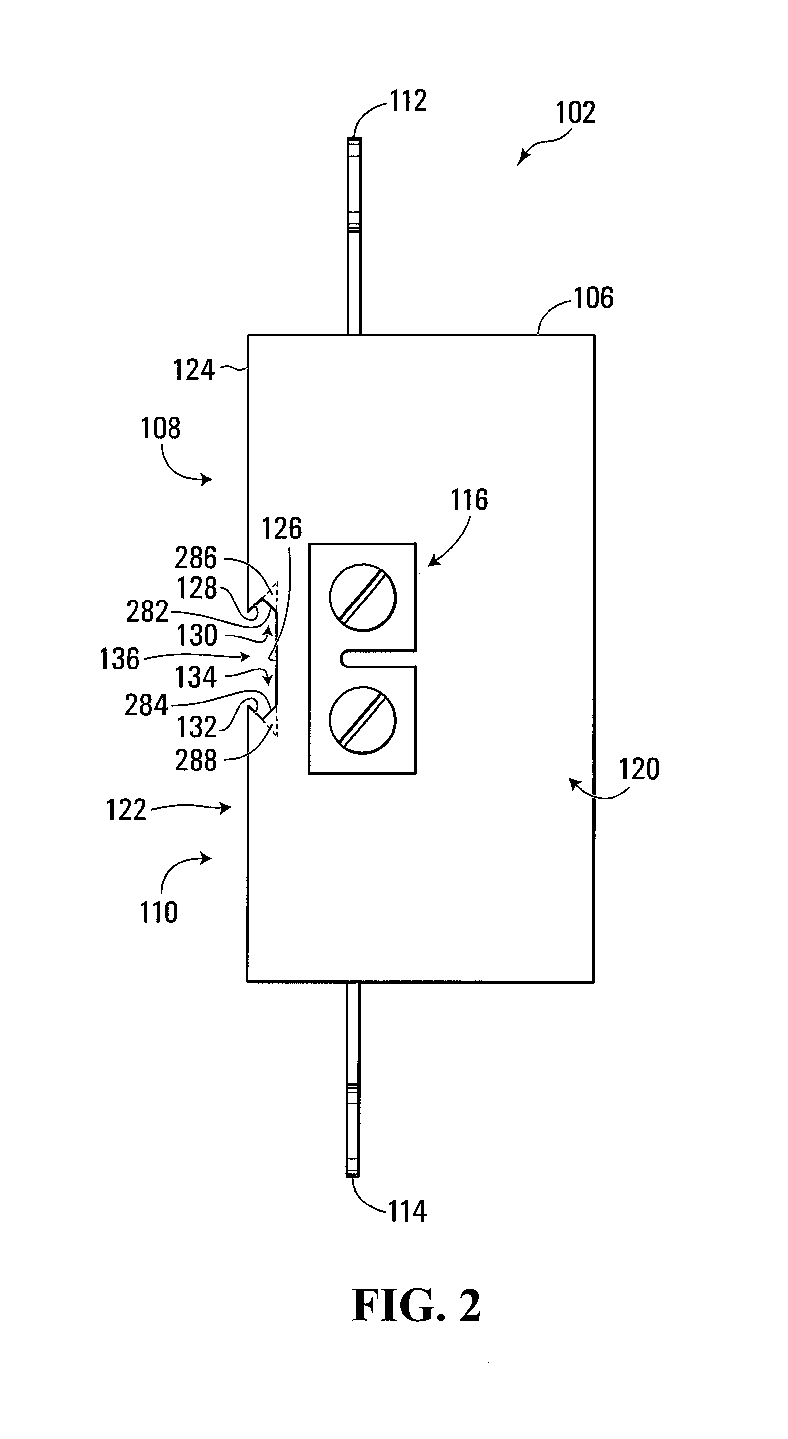
[0068]Referring to FIG. 1, an illustrative electrical system device composite is shown generally at 100 and includes an electrical system device shown generally at 102 and an indicia-bearing body 104. In the embodiment shown, the electrical system device 102 includes an electrical system device body 106 having first and second electrical receptacles shown generally at 108 and 110 for receiving and electrically coupling with an electrical plug (not shown). The electrical system device body 106 also has first and second mounting members 112 and 114 for receiving respective fasteners (not shown) to mount the electrical system device body 106 to an electrical system device box mounted to a wall (not shown), and the electrical system device body 106 is thus wall-mountable, although it will be appreciated that the electrical system device body 106 may be mounted on structures other than walls. The electrical system device body 106 also includes an electrical connector shown generally at 1...


PUM


Abstract

An illustrative electrical system device includes a mountable electrical system device body defining a retaining region between first and second retaining surfaces for retaining an indicia-bearing body. The retaining region extends to at least one of first and second opposite sides of the electrical system device body to receive the indicia-bearing body from the at least one of the first and second opposite sides, indicia-bearing bodies, and a kit including an electrical system device and an indicia-bearing body, are also disclosed.

Description

RELATED APPLICATION[0001]This application claims priority to Canadian Patent Application No. 2,678,609 filed on Sep. 23, 2009, which is incorporated by reference herein in its entirety.BACKGROUND[0002]1. Field[0003]The invention relates generally to electrical system devices, and more particularly to indicia-bearing bodies, electrical system devices configured to retain such indicia-bearing bodies, and kits including the same.[0004]2. Related Art[0005]In some circumstances, it may be desirable to associate information with a particular electrical system device, such as an electrical switch or receptacle, for example. Such information may include, for example, an identifier of a circuit associated with the electrical system device, information regarding proper use or function of the electrical system device, or other information relating to safe and effective use of the electrical system device.[0006]One known electrical system device faceplate has label cover mounting recesses each ...

Claims


Application Information

Patent Timeline
IPC IPC(8): G09F13/04H05K7/02
CPCH01H9/18H01H9/182H01R2103/00H01R24/76H01R25/00H01R13/465
Inventor EKINS, WILLIAM JAMES
Owner EKINS WILLIAM JAMES
Why Eureka
Try Eureka