Counterbalance mechanism

a technology of counterbalance and mechanism, which is applied in the field of counterbalances, can solve the problems of cost, complexity, cost, and complexity of the tanning bed lid, and achieve the effects of avoiding damage to the cover, avoiding oxidation, and avoiding oxidation

Active Publication Date: 2012-08-02
WEBER KNAPP
View PDF18 Cites 13 Cited by
  • Summary
  • Abstract
  • Description
  • Claims
  • Application Information

AI Technical Summary

Problems solved by technology

If the foregoing assistance is not provided, the cover or enclosure may be difficult if not impossible to move, or in the alternative, a situation may exist where the user can not control the movement of the cover thereby resulting in damage to the cover.
Production variations in these devices cause variability in the location of the center of gravity of the tanning bed lid.
Heretofore, tradeoffs between expense, complexity and performance were required.

Method used


Image

  • Counterbalance mechanism
  • Counterbalance mechanism
  • Counterbalance mechanism

Examples


Embodiment Construction

[0033]At the outset, it should be appreciated that like drawing numbers on different drawing views identify identical, or functionally similar, structural elements of the invention. While the present invention is described with respect to what is presently considered to be the preferred aspects, it is to be understood that the invention as claimed is not limited to the disclosed aspects.

[0034]Furthermore, it is understood that this invention is not limited to the particular methodology, materials and modifications described and as such may, of course, vary. It is also understood that the terminology used herein is for the purpose of describing particular aspects only, and is not intended to limit the scope of the present invention, which is limited only by the appended claims.

[0035]Unless defined otherwise, all technical and scientific terms used herein have the same meaning as commonly understood to one of ordinary skill in the art to which this invention belongs. As used herein, “...


PUM


Abstract

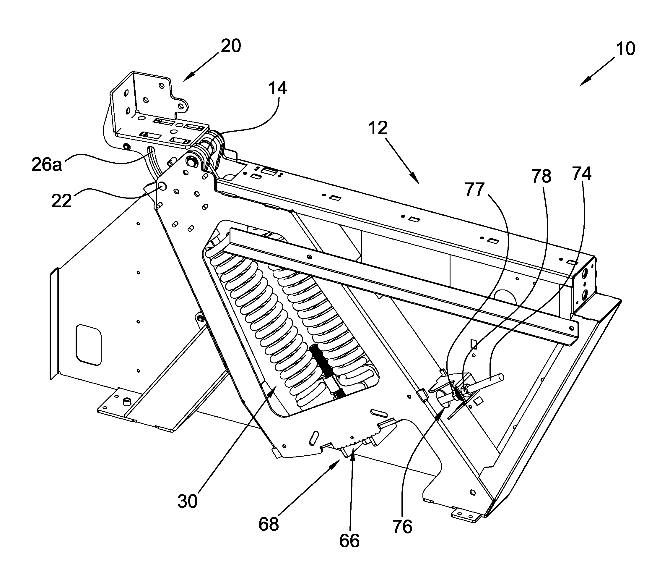
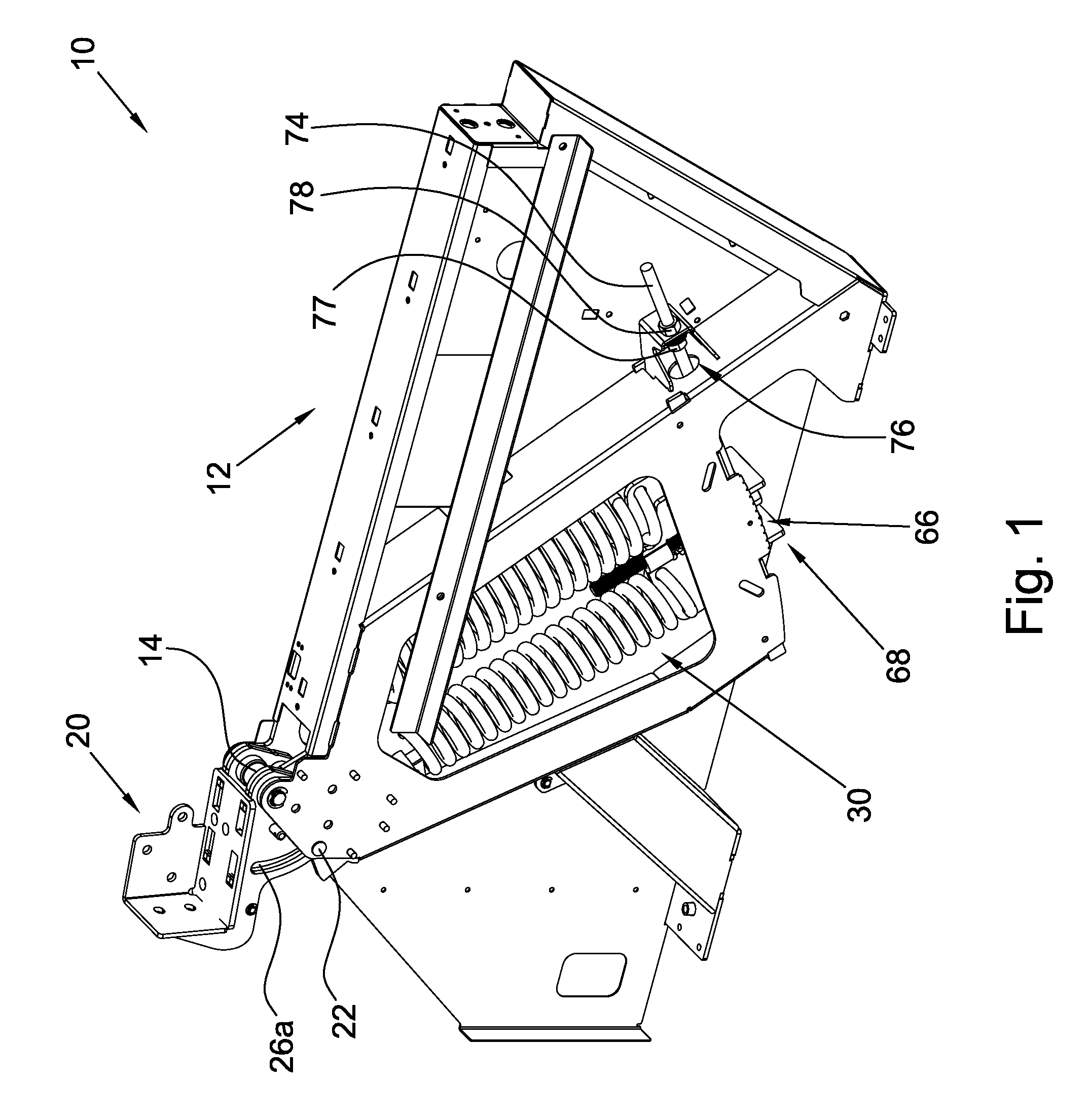
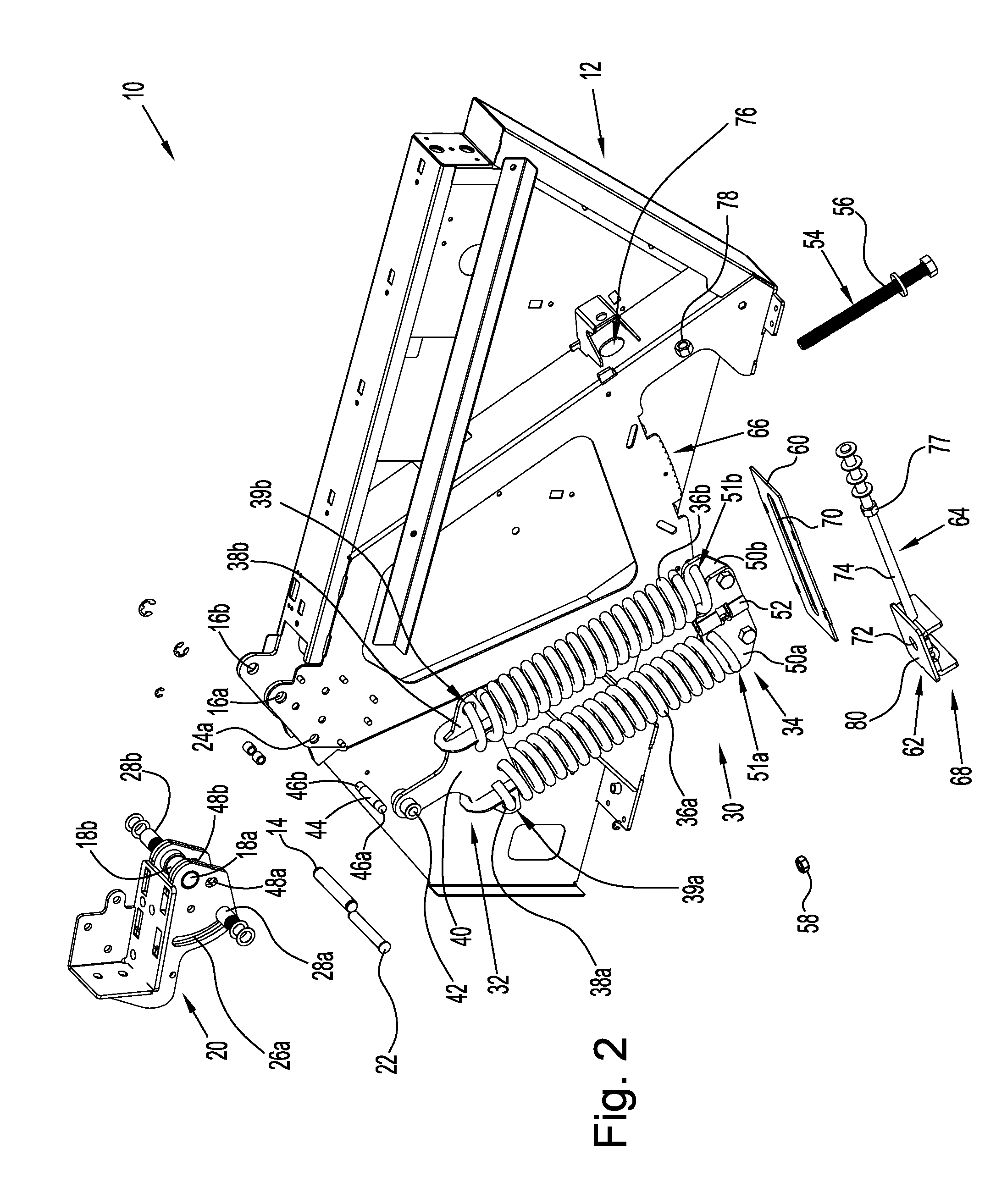
A counterbalance mechanism including: a housing having a first aligned pair of through holes and a second aligned pair of through holes; a pivot nose having a third aligned pair of through holes, a fourth aligned pair of through holes and an aligned pair of arcuate slots; an energy storage device having first and second spring mounts and at least one spring, the first spring mount having at least one first flange and a pivot flange having a fifth through hole, the second spring mount having at least one second flange and a sixth through hole and the at least one spring includes first and second ends, the first end is secured to the at least one first flange and the second end is secured to the at least one second flange; a first pivot pin disposed in the first aligned pair of through holes and the third aligned pair of through holes; a stop member disposed in the second aligned pair of through holes and the aligned pair of arcuate slots; a second pivot pin disposed in the fourth aligned pair of through holes and the fifth through hole; a force magnitude adjuster arranged to control a force of the at least one spring; and, a force angle adjuster arranged to control a force direction of the at least one spring.

Description

FIELD OF THE INVENTION[0001]The invention broadly relates to counterbalances, more specifically to adjustable counterbalances, and even more particularly to an adjustable counterbalance including force magnitude adjustment and force angle or direction adjustment.BACKGROUND OF THE INVENTION[0002]Counterbalance mechanisms including a pair of interconnected parallelograms linkages, which are provided with counterbalance springs, are well known, as disclosed in U.S. Pat. Nos. 2,131,693; 3,426,190; 4,447,031; and, 5,180,136, which patents are incorporated by reference in their entireties herein. Counterbalance mechanisms having individually adjustable counterbalance springs are also known in the art, as shown in U.S. Pat. No. 4,447,031. It is also known to provide a mechanism for controlling vertical movement of a surface, such as a desk, a table top or a shelf relative to a supporting base wherein a counterbalance mechanism is provided to balance at least part of the weight of the surfa...

Claims


Application Information

Patent Timeline
Patent Type & Authority Applications(United States)
IPC IPC(8): E05F1/08E05F1/00
CPCA61N5/0614A61N2005/0633E05F1/1075E05Y2201/488E05Y2201/492Y10T16/82E05Y2600/20E05Y2800/21E05Y2900/60E05Y2201/618Y10T16/84E05Y2201/702
Inventor HONSBERGER, BRENT A.WAXHAM, WARREN A.
Owner WEBER KNAPP
Why Eureka
Try Eureka