Non-lethal variable distance electronic timed payload projectile ammunitions

a technology of electronic timed payload and projectile ammunition, which is applied in the direction of ammunition fuzes, electric fuzes, lighting and heating apparatus, etc., can solve the problems of material burn, mechanical pressed fuses are also hard to detonate, and the projectile body of current mechanical fuses used to date can be unpredictable, so as to reduce the base drag

Active Publication Date: 2012-08-23
DEFENSE TECH
View PDF5 Cites 11 Cited by
  • Summary
  • Abstract
  • Description
  • Claims
  • Application Information

AI Technical Summary

Benefits of technology

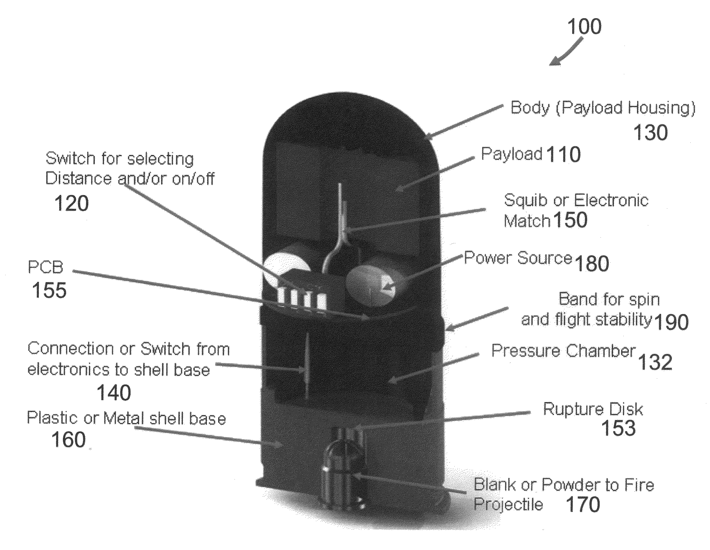
[0007]An embodiment of the present invention provides a non-lethal variable distance electronic timed payload projectile ammunition. The non-lethal variable distance electronic timed payload projectile ammunition is designed to detonate or activate a payload at a distance that is pre-set by the operator before the ammunition is loaded into a launcher. The operator arms the non-lethal payload projectile ammunition and sets the travel distance of the projectile body of the ammunition with a switch. After the projectile ammunition is armed and set for the correct distance the user loads the projectile ammunition into the launcher. When the ammunition is fired, a connection will be activated starting the timing process. An explosion or blast will propel the projectile body out of the launcher. The timing that was preset by the operator starts to countdown after the non-lethal projectile ammunition is fired. Once the pre-determined set time is reached, an electronic match or squib circuit (or squib) activates the payload. The electronics in the circuit will detonate or dissipate the payload at the intended distance allowing for maximum or increased non-lethal effectiveness to the intended target.
[0018]In one embodiment, the non-lethal variable distance electronic timed payload projectile ammunition further includes the projectile body with a boat tail for reducing base drag.
[0019]In one embodiment, the projectile body has a driving band to engage rifling of a launcher barrel to spin the projectile body for flight stability.
[0026]Another embodiment of the present invention provides a method for varying an initiation time for a non-lethal variable distance electronic timed payload projectile ammunition. The method includes: grounding a projectile body for carrying a non-lethal payload to a conductive shell; switching a timing circuit out of a dormant state; selecting an ignition delay period of the timing circuit from a plurality of selectable delay periods; separating the projectile body from the conductive shell by firing the ammunition; allowing the timing circuit to begin timing out the selected ignition delay period; and allowing enough current to pass to an electronic igniter to initiate the non-lethal payload once the end of the selected ignition delay period has been reached.

Problems solved by technology

The current mechanical fuse projectile bodies used to date can be unpredictable and have varying distance result.
The material burn and mechanical pressed fuses are also hard set to detonate at a preset time that is built into the ammunition and is not adjustable.

Method used


Image

  • Non-lethal variable distance electronic timed payload projectile ammunitions
  • Non-lethal variable distance electronic timed payload projectile ammunitions
  • Non-lethal variable distance electronic timed payload projectile ammunitions

Examples


Embodiment Construction

[0047]In the following detailed description, only certain exemplary embodiments of the present invention are shown and described, by way of illustration. As those skilled in the art would recognize, the described exemplary embodiments may be modified in various ways, all without departing from the spirit or scope of the present invention. Accordingly, the drawings and description are to be regarded as illustrative in nature, and not restrictive. Like reference numerals designate like elements.

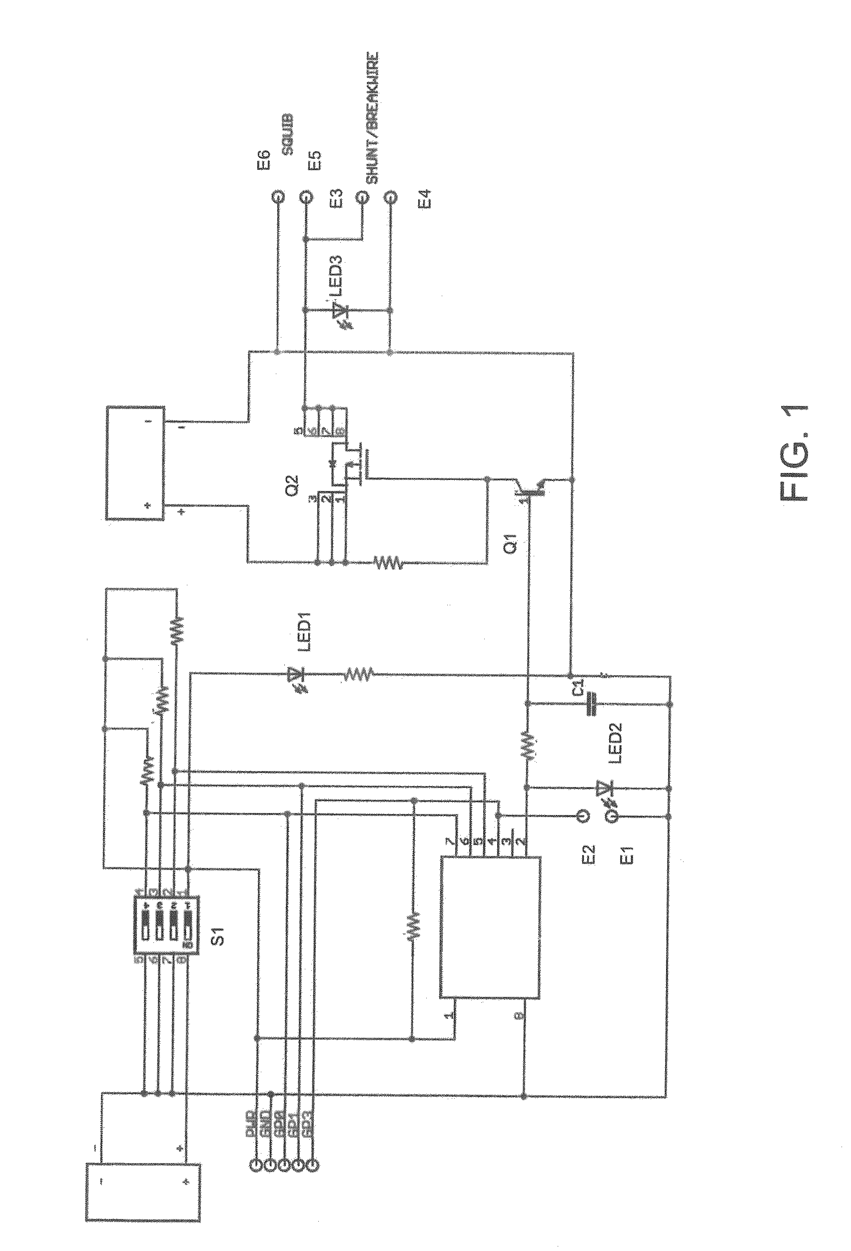
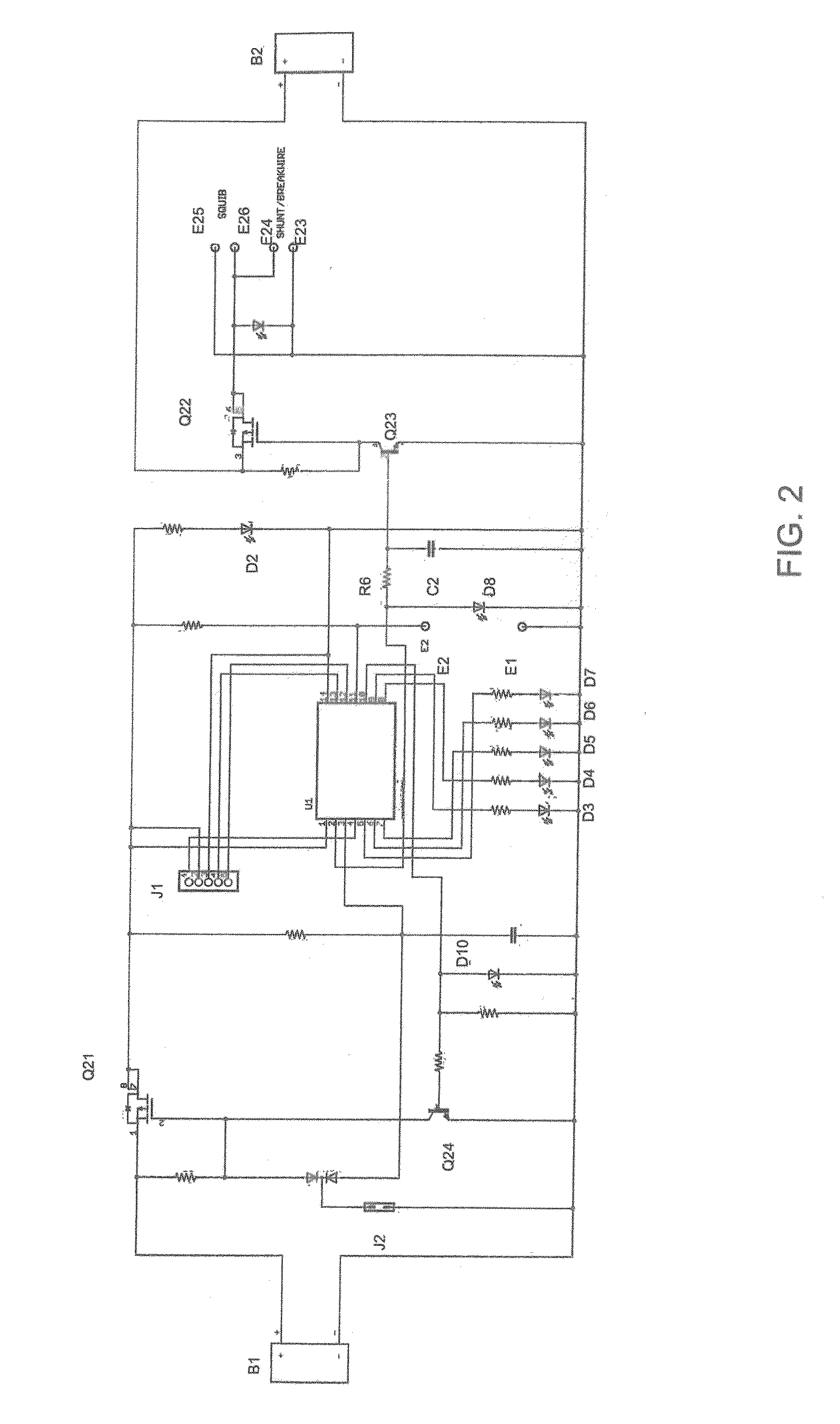
[0048]An embodiment of the present invention provides a non-lethal variable distance electronic timed payload ignition projectile ammunition that includes a timing circuit on a printed circuit board. The circuit's purpose is to allow for an adjustable time delay. The delay is the time between the firing of the non-lethal variable distance electronic timed payload projectile ammunition composed of a projectile body containing this timing circuit and the time of activation of the charge contained...


PUM


Abstract

A non-lethal projectile used to immobilize, impair, disorient, or distract a live target. The non-lethal projectile can also be used as a signaling device. In one embodiment, a non-lethal payload carrying projectile that is detonated at a set distance determined and set by the operator. The distance is electronically controlled and can be set in the field seconds before the projectile is fired.

Description

CROSS-REFERENCE TO RELATED APPLICATIONS[0001]This application claims priority to and the benefit of U.S. Provisional Application No. 61 / 190,603, filed on Aug. 29, 2008, the entire content of which is incorporated herein by reference.FIELD OF THE INVENTION[0002]The present invention relates generally to the field of non-lethal projectile ammunitions used to immobilize, impair, disorient, and / or distract live targets. These non-lethal projectile ammunitions can also be used as signaling devices.BACKGROUND OF THE INVENTION[0003]Non-lethal projectile bodies are often shot at or near human targets at high velocities and at long and varying distances. It is imperative that the detonation or dispersion of the payload of the projectile body be near the target. The detonation distance is controlled and determined by the time at which the payload is activated as well as the travel velocity of the non-lethal projectile body. The current mechanical fuse projectile bodies used to date can be unp...

Claims


Application Information

Patent Timeline
Patent Type & Authority Applications(United States)
IPC IPC(8): F42B12/46F42C9/00F42C21/00F42B10/44F42B14/02F42B5/02F42B12/02F42C11/00
CPCF42B12/40F42B12/46F42B12/50F42C11/001F42C19/06F42C17/02F42C17/04F42C19/02F42C11/065
Inventor KRAMER, MICHAELRUTZ, COREY
Owner DEFENSE TECH
Why Eureka
Try Eureka