Operational amplifier

a technology of operation amplifier which is applied in the direction of gated amplifier, amplifier with semiconductor devices only, amplifier with semiconductor devices, etc., can solve the problems of voltage buffer deviating and voltage buffer not being able to drive the load, so as to prevent voltage redistribution and charge coupling

Active Publication Date: 2012-10-04
NOVATEK MICROELECTRONICS CORP
View PDF1 Cites 1 Cited by
  • Summary
  • Abstract
  • Description
  • Claims
  • Application Information

AI Technical Summary

Benefits of technology

[0007]The invention is directed to a coupling effect reduction apparatus and an operational amplifier applying the same. Compared to a conventional operational amplifier, the coupling effect reduction apparatus and operational amplifier of the present invention are advantageously capable of having an operational amplif

Problems solved by technology

For example, when an output enable switch is turned off, an open circuit is accordingly presented between the voltage buffer and the load such that the voltage buffer is incapable of driving the load.
For a voltage buffer having an internal circuit design wit

Method used


Image

  • Operational amplifier
  • Operational amplifier
  • Operational amplifier

Examples


Embodiment Construction

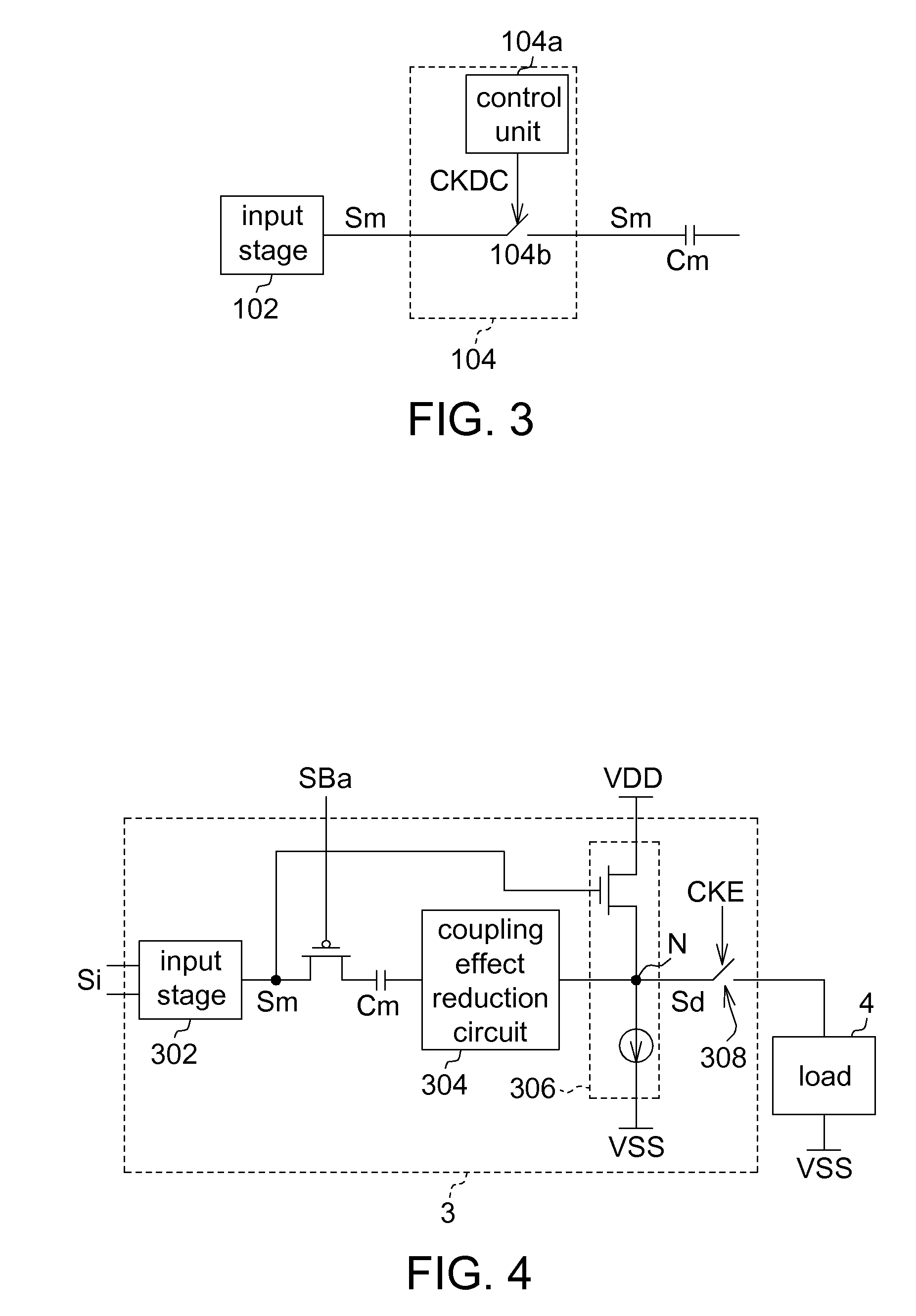
[0015]A coupling effect reduction apparatus according to an embodiment of the present invention is applied in an operational amplifier. The coupling effect reduction apparatus is capable of having the operational amplifier separated from voltage redistribution and charge coupling effects achieved with switching operations, e.g. turning on or turning off, of an output enable switch.

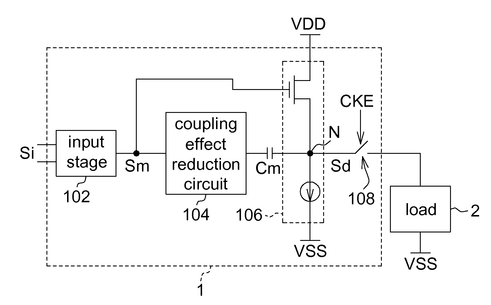
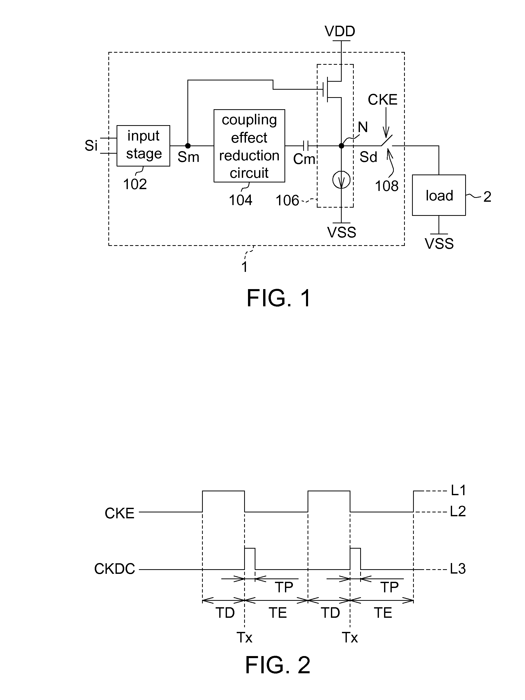
[0016]FIG. 1 shows a block diagram of an operational amplifier according to an embodiment of the present invention. An operational amplifier 1, serving as an output buffer for driving a load 2, comprises an input stage 102, a coupling effect reduction circuit 104, an output stage 106, an output enable switch 108, and an internal circuit Cm. The input stage 102 provides an intermediate signal Sm according to an input signal Si. For example, the input stage 102 is a main gain stage amplifying circuit of the operational amplifier 1. The output stage 106 comprises an output node N and provides a driving signal...


PUM


Abstract

An operational amplifier includes an input stage, an output stage, an output enable switch, an internal capacitor, a coupling effect reduction circuit. The input stage provides an intermediate signal according to an input signal. The output stage, including an output node, provides a driving signal according to the intermediate signal. The output enable switch is turned on during an output enable period, having a start time point, to drive a load with the driving signal. The internal capacitor is coupled between the input stage and the output stage. The coupling effect reduction circuit, coupled between the internal capacitor and the output node or between the internal capacitor and the input stage, is turned off during an operational period starting from the start time point, to prevent coupling charge generated when the output enable switch is turned on from affecting operational voltage levels of the input stage.

Description

[0001]This application claims the benefit of Taiwan application Serial No. 100110852, filed Mar. 29, 2011, the subject matter of which is incorporated herein by reference.BACKGROUND OF THE INVENTION[0002]1. Field of the Invention[0003]The invention relates in general to a coupling effect reduction apparatus, and more particularly to a coupling effect reduction apparatus for reducing a charge coupling effect in an operational amplifier.[0004]2. Description of the Related Art[0005]In current technologies, an operational amplifier is often used as a voltage buffer that drives a load subsequently connected therefrom with a voltage. A voltage buffer generally functions with an output enable switch to perform associated timing controls. For example, when an output enable switch is turned off, an open circuit is accordingly presented between the voltage buffer and the load such that the voltage buffer is incapable of driving the load. In contrast, when the output enable switch is turned on...

Claims


Application Information

Patent Timeline
IPC IPC(8): H03F3/16
CPCH03F3/45475H03F3/45928H03F2203/7221H03F3/72H03F3/505
Inventor HUNG, WEI-HSIANGLIN, CHIA-HUNG
Owner NOVATEK MICROELECTRONICS CORP
Why Eureka
Try Eureka