Hydraulic turbo accelerator apparatus

Active Publication Date: 2012-10-25
HYDRACHARGE
View PDF32 Cites 25 Cited by
  • Summary
  • Abstract
  • Description
  • Claims
  • Application Information

AI Technical Summary

Benefits of technology

[0023]It is an object of the present invention to provide means to rapidly accelerate the rotating group of a turbocharge

Problems solved by technology

Slow acceleration of these turbines known as “turbo lag” has always been an issue as turbine devices, although capable of large power output at very high speed, are low torque output devices on relative scale to positive as “turbo lag” has always been an issue as turbine devices although capable of large power output at very high speed are low torque output devices on relative scale to positive displacement devices such as gear, gerotor, vane or piston hydraulic motors.
These forgoing known hydraulic turbines create more torque than an equivalent gas driven turbine as the density of the oil is roughly 1000 times greater than air, but still are relatively poor at creating angular acceleration.
They create a very potent configuration in upper engine speed ranges but the inertia of the high speed impellers as reflected through their step up gearboxes to the drive pulley create exceedingly high loads on the belt upon rapid engine speed changes.
They are also at the disadvantage that the pressure or boost created by the spinning impeller is a function of speed squared.
Given that the mechanism permanently couple

Method used


Image

  • Hydraulic turbo accelerator apparatus
  • Hydraulic turbo accelerator apparatus
  • Hydraulic turbo accelerator apparatus

Examples


Embodiment Construction

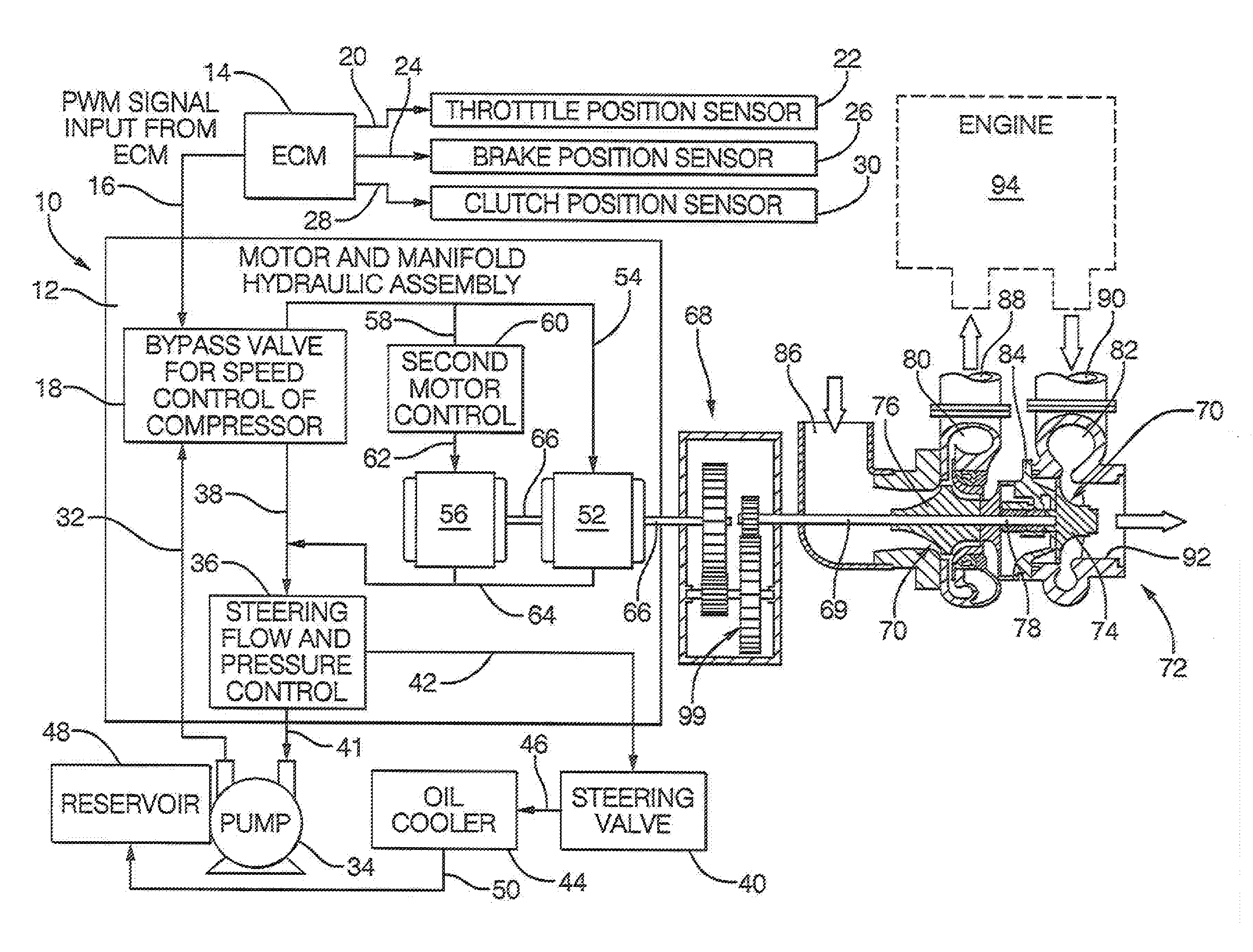
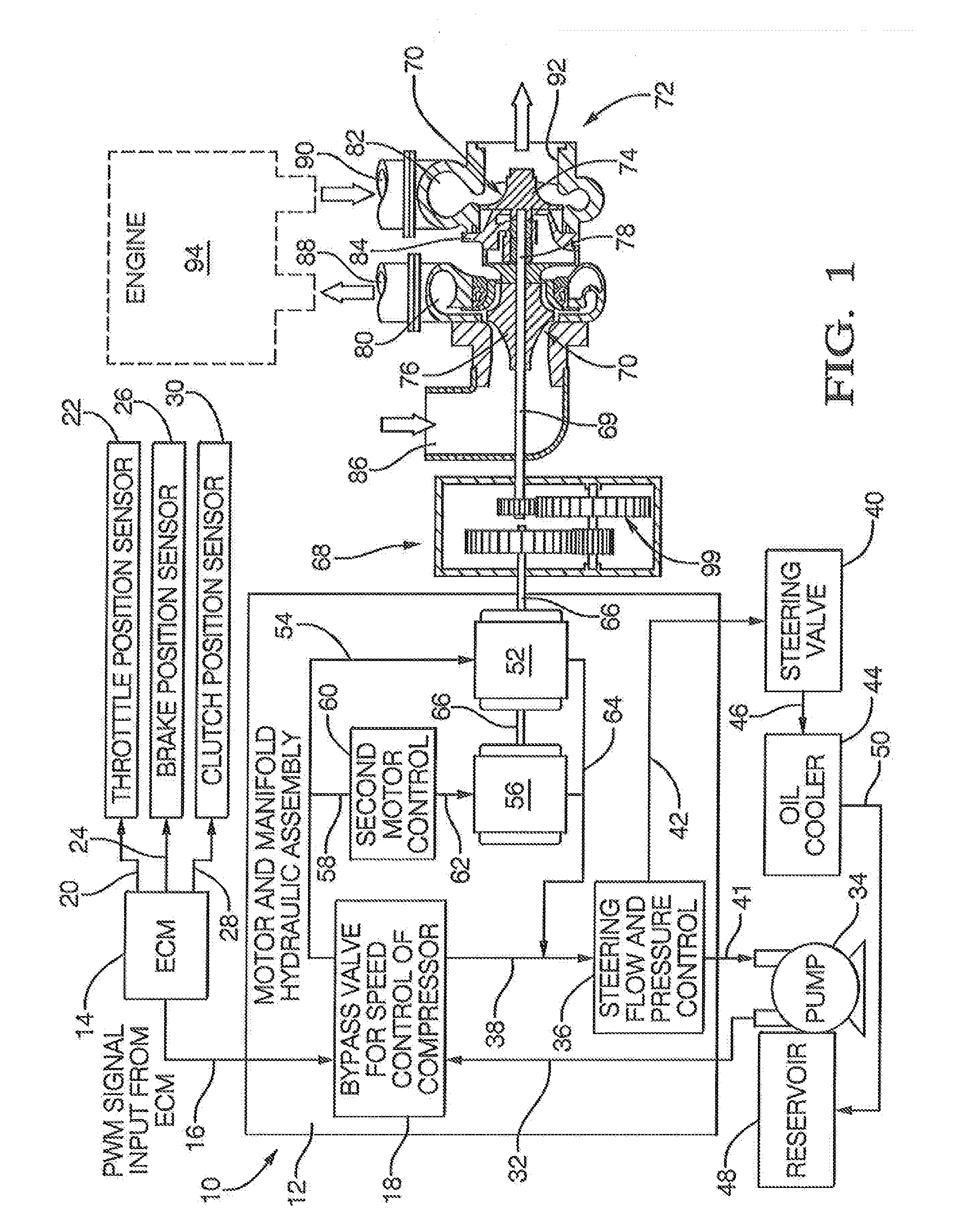
[0042]The present invention is identified by the applicant as a HydraCharger™ or forced air induction system, which re-deploys existing automotive radiator fan drive technology. The forced air induction system is cost effective and easily adaptable for a wide range of vehicle applications. The system is electronically controlled, hydraulically powered and remotely mounted for easy packaging. Independence from the vehicle engine and exhaust reduces vehicle level costs and avoids adverse emissions issues.

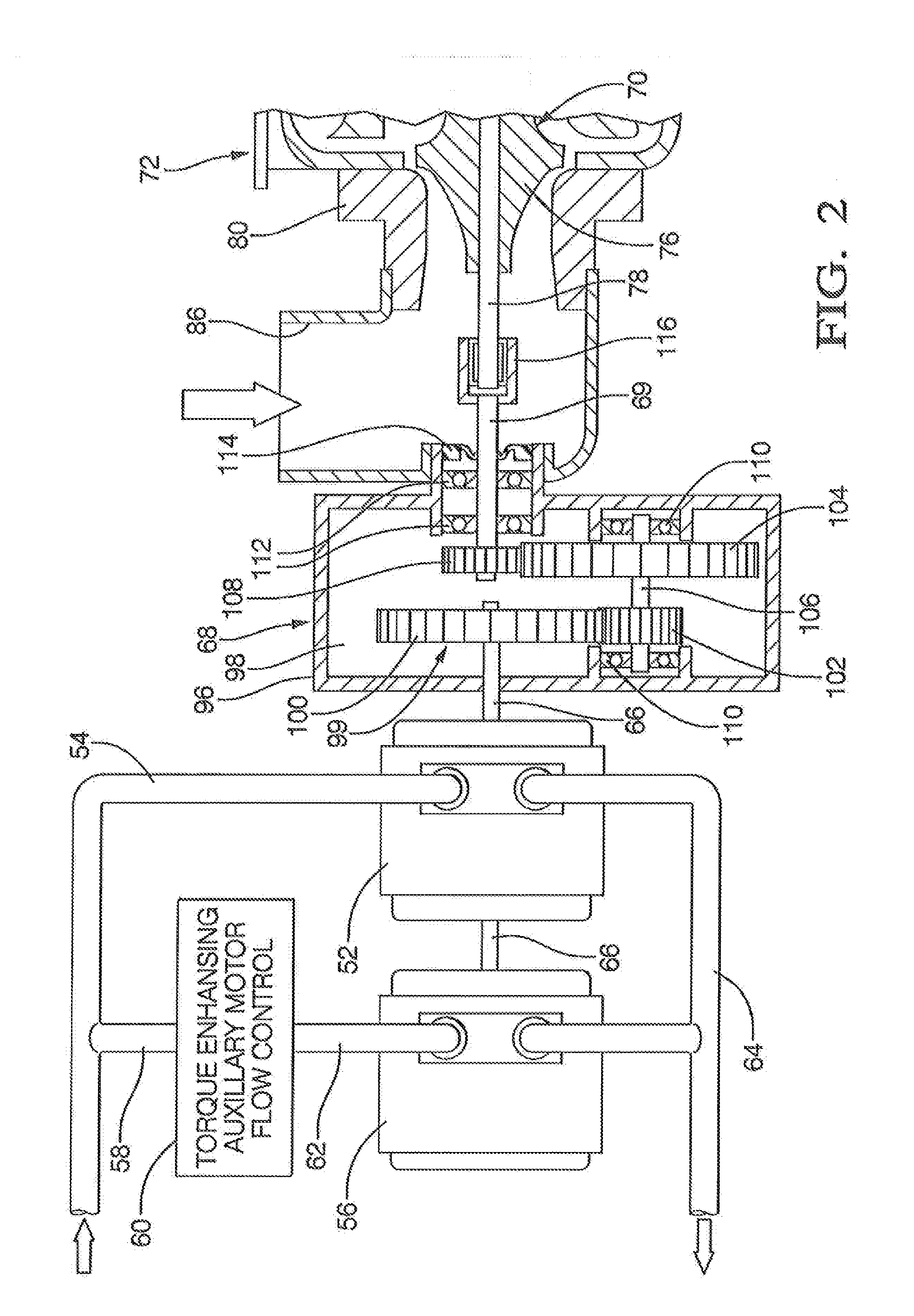
[0043]The present invention provides supercharger response on electronic command. The forced air induction system's variable positive displacement hydraulic drive delivers full torque virtually instantaneously upon command from an associated electronic control module (ECM). This accelerates a reliable, efficient and low cost centrifugal compressor to a speed required to create boost in under 300 ms. At low throttle demand, the engine returns to naturally aspirated mode through the unp...


PUM


Abstract

A hydraulic drive assists to increase the acceleration rate of a turbocharger impeller/turbine shaft assembly and provide a secondary means of driving the compressor impeller at lower engine speeds where exhaust gases alone does not generate adequate shaft speeds to create significant induction boost. The hydraulic circuit includes a dual displacement motor, which provides high torque for acceleration yet converts to a single motor for high-speed operation. When the exhaust driven turbine function allows compressor speeds, beyond which the hydraulic system can contribute, a slip clutch allows disengagement of the hydraulic drive. The hydraulic circuit is integrated with the power steering circuit to conserve energy and supportive components such as lines and reservoir. In an alternative embodiment, there is no turbocharger and the hydraulic drive provides means of forced induction air alone.

Description

RELATED PATENT APPLICATION[0001]This application claims priority to U.S. provisional patent application Ser. No. 61 / 283,697 filed 8 Dec. 2009, entitled “Hydraulic Turbo Accelerator Apparatus”.TECHNICAL FIELD[0002]Many automotive engines, particularly diesels, are equipped with a method of boosting the inlet air density in order achieve greater power per unit engine displacement. The large majority of these systems are turbocharged diesels with a smaller market share consisting of supercharged gasoline power trains. Turbochargers have an efficiency advantage in that the power to drive the air compressor is obtained from exhaust energy, which is preferable to accessory belt loading, however they struggle with response issues, which limit vehicle acceleration capabilities. Further, the increased exhaust pressures and temperatures incurred with turbocharger applications lead to heavier exhaust systems which, along with the thermal mass of the turbocharger itself, tend to create emission...

Claims


Application Information

Patent Timeline
IPC IPC(8): F02B33/40F02B37/10
CPCF02B37/10Y02T10/144F02B39/085F02B39/08Y02T10/12
Inventor BUSCHUR, JEFFREY J.LEEMHUIS, RICHARD S.SHLOFF, DONALD G.
Owner HYDRACHARGE
Why Eureka
Try Eureka