
Eureka
For R&D, Eureka makes reading and utilizing patents & technical documents easy.
Eureka AIR
Designed for self-driven R&D workflows. Generate viable solutions, solve complex R&D challenges, empower your innovation with AI.

Eureka Materials
Designed for material experts only. Revolutionize your material R&D, from search, analyze, to developing new materials.

TechResearch
Generate reliable direction feasibility study reports for your R&D in just a few steps.

TechSeek
Discover and master advanced knowledge NOW. Basics, ideas, possibilities, all at once.

TechMind
As an expert in R&D Theories, TechMind can generates customized viable solutions instantly.

TechRisk
Analyze your overall solution with one click, know your potential R&D risks in advance.

TechMonitor
Get weekly tech updates, stay abreast of the latest tech innovations and key insights.
Pipe Conditioning Tool
- Summary
- Abstract
- Description
- Claims
- Application Information
AI Technical Summary
Benefits of technology
Problems solved by technology
Method used
Image

Examples
Example
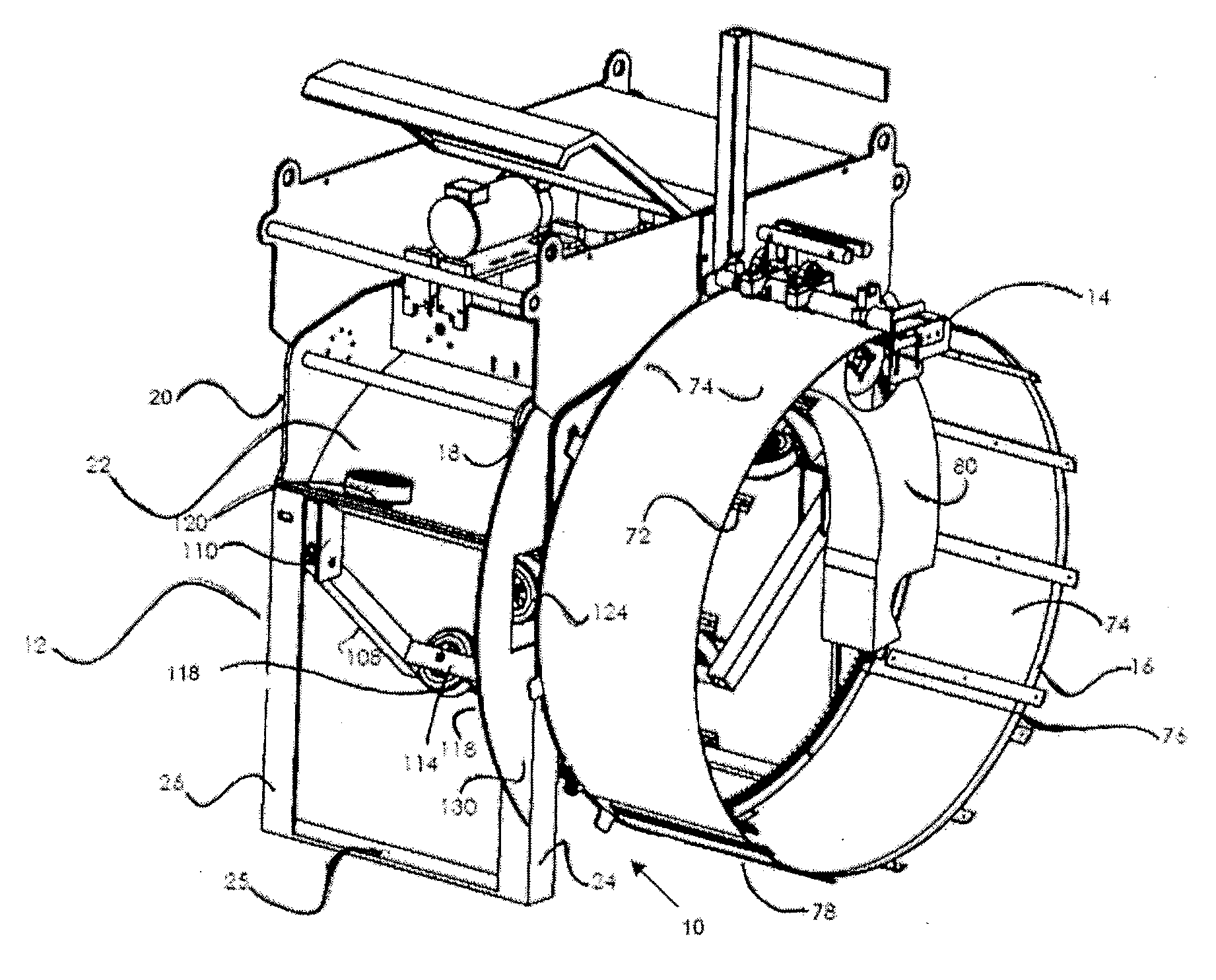
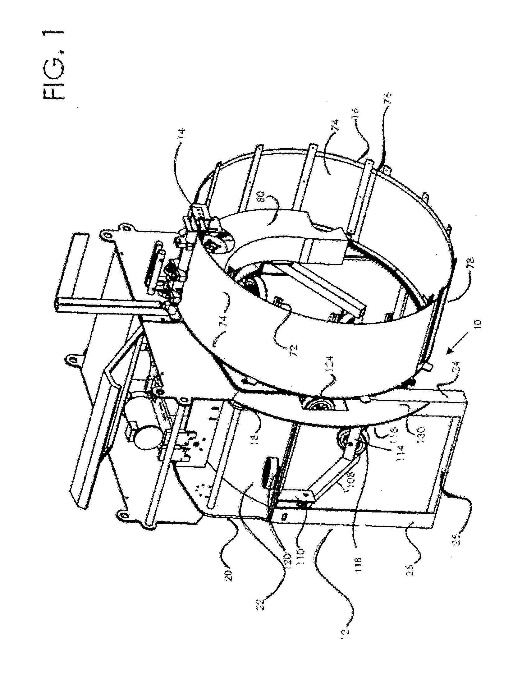
[0038]Initially, an embodiment will be described in the context of a machine to condition and / or coat a pipe after the previous coating has been removed, but, as will be appreciated from the subsequent embodiments, certain features may be utilized for machines to remove coating from a pipe and to apply a coating to a girth weld.
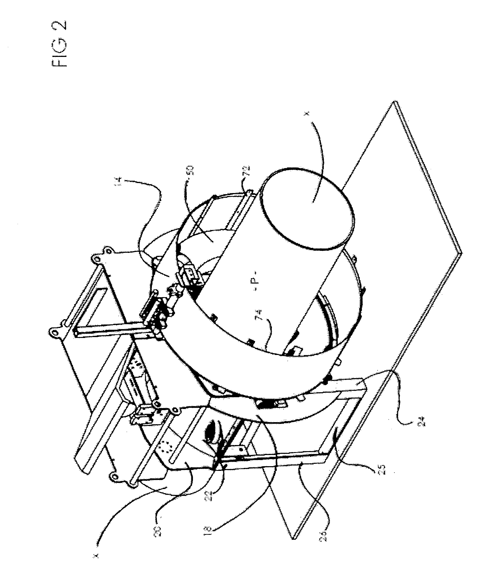
[0039]Referring to the drawings, a pipe conditioning tool 10 used to prepare a surface of a pipe has a support frame 12 that carries a work head 14 and a shroud 16. As can best be seen from FIG. 4, the tool 10 is arranged to straddle a pipe P so as to be moveable along the longitudinal axis x-x of the pipe P and perform work on the exterior surface of the pipe P to condition the surface. The pipe P may be an exposed length of an existing pipe, or may be a new pipe being prepared for installation. Such conditioning can include removal of existing coatings, surface preparation and recoating of the exterior surface, although in the embodiment shown in FIGS. 1-12...
PUM
| Property | Measurement | Unit |
|---|---|---|
| Flexibility | aaaaa | aaaaa |
Abstract
Description
Claims
Application Information
 - R&D Engineer
- R&D Manager
- IP Professional
- Industry Leading Data Capabilities
- Powerful AI technology
- Patent DNA Extraction
Browse by: Latest US Patents, China's latest patents, Technical Efficacy Thesaurus, Application Domain, Technology Topic, Popular Technical Reports.
© 2024 PatSnap. All rights reserved.Legal|Privacy policy|Modern Slavery Act Transparency Statement|Sitemap|About US| Contact US: help@patsnap.com