
Vacuum cleaner

Active Publication Date: 2012-12-20
KONINKLIJKE PHILIPS ELECTRONICS NV
View PDF0 Cites 5 Cited by
  • Summary
  • Abstract
  • Description
  • Claims
  • Application Information

AI Technical Summary

Benefits of technology

[0006]It is an object of the invention to provide a vacuum cleaner of the above mentioned kind having improved separation efficiency.

Problems solved by technology

If the drag forces on an airborne particle outweigh the centrifugal forces on said particle, the particle enters the separator, thereby harming the overall separation efficiency.

Method used


Image

  • Vacuum cleaner
  • Vacuum cleaner
  • Vacuum cleaner

Examples


Embodiment Construction

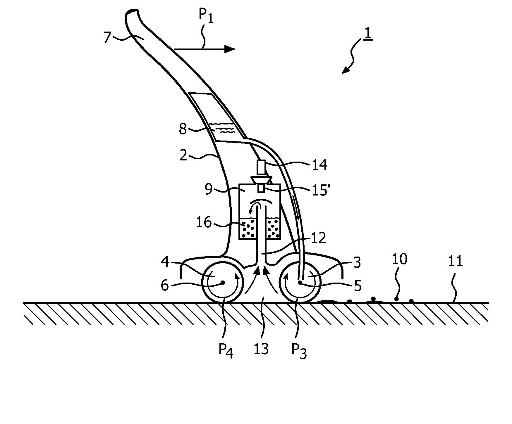
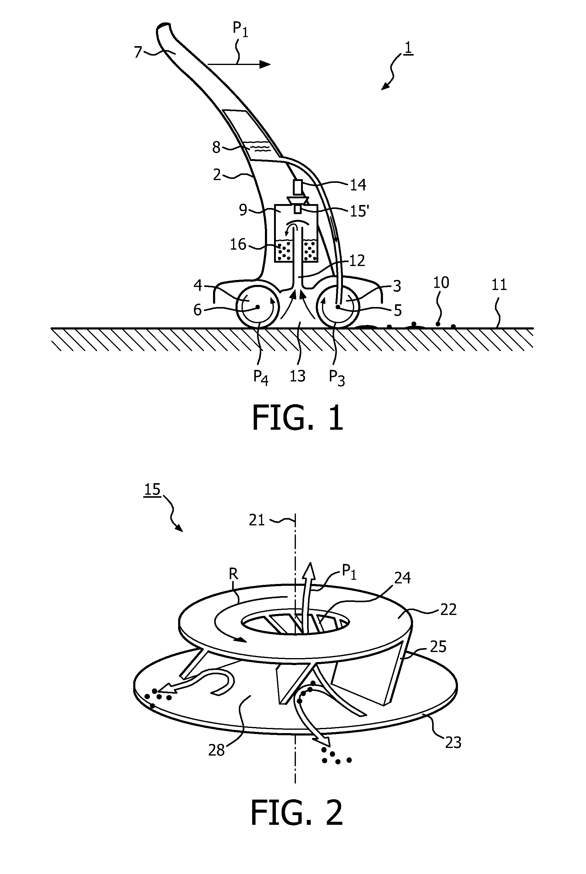
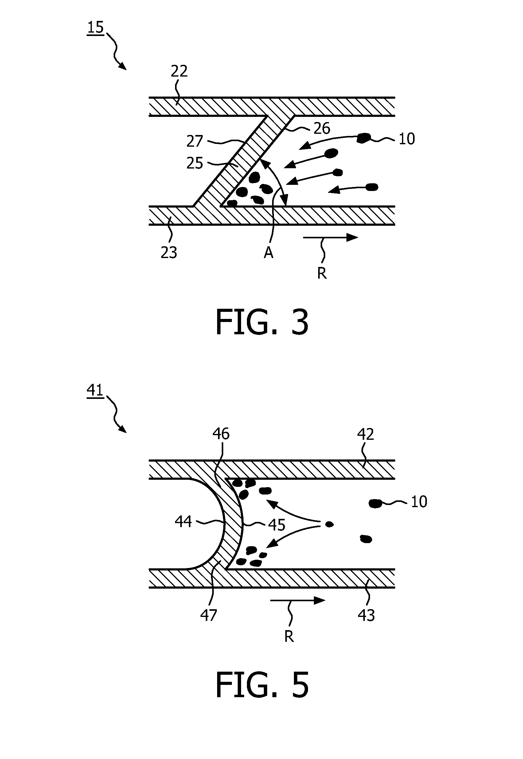
[0038]In FIG. 6 a cross-section of a vane 25 of a separator 15 is schematically depicted. The vane 25 is rotating in a clockwise direction around an axis of rotation 21 of the separator 15. The direction of rotation is indicated by a curved arrow R. A practical embodiment of the separator 15 is in general equipped with a number of such vanes; however, in FIG. 6 only one vane is depicted. If a trajectory 32 of an air molecule flowing into the separator, i.e. a flow line, is considered, a distinction can be made between a so-called leading face 26 and trailing face 27 of the vane 25. This leads to a side or part of the vane that first approaches the air flowing along flow line 32 when the separator is rotating; this side is referred to as the leading face of the vane. As the air continues its path around the vane it will subsequently reach the other side of the vane which is referred to as the trailing face 27 of the vane. The leading face 26 of a vane is the side of the vane which fa...


PUM


Abstract

A vacuum cleaner (1) comprises an inlet (13), an outlet, a fan (14) for creating a flow of air through the vacuum cleaner (1) by drawing air to be cleaned through the inlet (13) into the vacuum cleaner (1) and by exhausting air through the outlet outwardly of the vacuum cleaner (1) and a separator (15, 41). The separator (15, 41) is rotatably arranged around an rotation axis (21), for creating, during use, a column of rotating air to separate at least a portion of the airborne particles (10) from the flow of air. The separator (15, 41) includes a number of vanes (25, 44) for the creation of the column of rotating air, wherein each vane (25, 44) is provided with a leading face (26) and a trailing face (27). The leading faces (26) of the vanes (25, 44) are inclined with respect to the rotation axis (21) for conveying the airborne particles (10) at least in an axial direction.

Description

FIELD OF THE INVENTION[0001]The invention relates to a vacuum cleaner, comprisingan inlet for receiving, during use, air to be cleaned, the air to be cleaned being laden with airborne particles,an outlet for expelling air outwardly of the vacuum cleaner,a fan for creating a flow of air through the vacuum cleaner by drawing the air to be cleaned through the inlet into the vacuum cleaner and by exhausting air through the outlet outwardly of the vacuum cleaner anda separator rotatably arranged around an rotation axis, for creating, during use, a column of rotating air to separate at least a portion of the airborne particles from the flow of air, which separator includes a number of vanes for the creation of the column of rotating air, wherein each vane is provided with a leading face and a trailing face.BACKGROUND OF THE INVENTION[0002]Such a vacuum cleaner is known from U.S. 2004 / 0068826 A1. By the vacuum cleaner disclosed in U.S. 2004 / 0068826 A1 air with airborne particulates and wat...

Claims


Application Information

Patent Timeline
IPC IPC(8): A47L9/10
CPCA47L9/188A47L9/0081A47L9/1608A47L9/182
Inventor VAN DER KOOI, JOHANNES TSEARDVOORHORST, FOKKE ROELOFDE WIT, BASTIAAN JOHANNES
Owner KONINKLIJKE PHILIPS ELECTRONICS NV
Learn More