
Polymer microcolumn for gas or vapor separation, chromatography, and analysis

Active Publication Date: 2018-10-11
THE BOARD OF TRUSTEES OF THE UNIV OF ILLINOIS
View PDF0 Cites 3 Cited by
  • Summary
  • Abstract
  • Description
  • Claims
  • Application Information

AI Technical Summary

Benefits of technology

This patent describes a new way to make microcolumns for separating gas molecules. These microcolumns are easy to make, can be designed in various ways, and are highly efficient at separating gases. The methods also result in microcolumns with a unique hollow channel shape that improves separation efficiency and allows for uniform coating of the stationary phase. The use of a sacrificial fiber in the process also allows for microcolumns with different cross-sectional shapes, such as circular or elliptical. Overall, this patent provides a cost-effective and scalable method for making microcolumns that can be used in portable chromatographs and offer improved separation performance.

Problems solved by technology

Conventional GC systems are bulky, have high power consumption, and usually have very long analysis times, often in tens of minutes.
These factors have largely limited the use of GC to a laboratory environment; thus, obtaining immediate results from field or environmental samples is difficult.
Additionally, personnel who may respond to these situations are not generally trained scientists.
Conventional microcolumn fabrication processes are complicated and require the use of expensive equipment and hazardous reagents, contributing to very expensive microcolumns.
Lithography requires specialized equipment and may require the use of a cleanroom or involve hazardous chemicals.
Microcolumn cross sectional shape is an additional challenge.
For example, columns with rectangular cross-sections, the stationary phases may pool in the corners during the coating step, leading to band broadening and poor separation efficiency.

Method used


Image

  • Polymer microcolumn for gas or vapor separation, chromatography, and analysis
  • Polymer microcolumn for gas or vapor separation, chromatography, and analysis
  • Polymer microcolumn for gas or vapor separation, chromatography, and analysis

Examples


example 1

as Chromatography Microcolumns Produced with a Sacrificial Template

[0223]Introduction: Gas chromatography (GC) is a powerful tool for analyzing volatile samples, but traditional GC instruments are confined to laboratory use, due in large part to their bulk. The need to analyze volatile samples outside the laboratory and in real time has spurred the development of portable GC devices. Portable GC devices have already found commercial use in industrial and environmental applications, and there are ongoing efforts to further miniaturize the various components of GC instruments, including the GC column.

[0224]The first GC microcolumn was developed by Terry and Angell, who used photolithography to etch a channel into a silicon wafer.1 Since the invention of the silicon GC microcolumn, other researchers have continued to improve upon microcolumn designs and incorporate silicon GC microcolumns into portable GC instruments.2-5 The silicon chip-based GC microcolumns differ from traditional si...

example 2

tal Descriptions

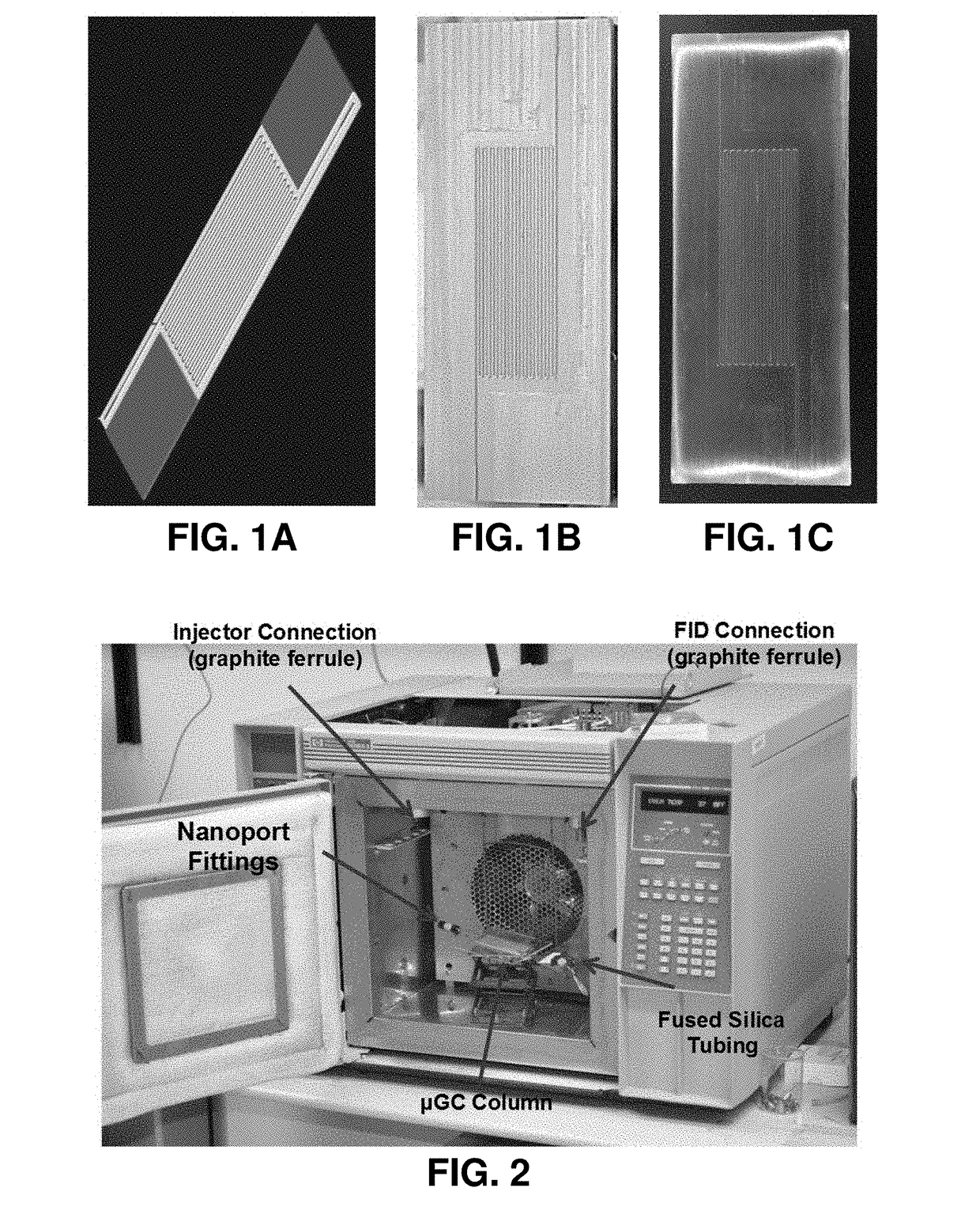
[0269]Optional supplemental descriptions and examples, for example relating to preparation of materials or testing procedures, may be found in Suslick, et al. (U.S. Patent Publication No. 2015 / 0300998) and in Rankin, et al. (J. M. Rankin, K. S. Suslick, “The development of a disposable gas chromatography microcolumn”, in Chemical Communications, year 2015, volume 51 (43), pages 8920-8923), each of which is incorporated herein in its entirety. Some exemplary supplemental descriptions are provided below.

[0270]A reusable mold may made by micromachining polychlorotrifluoroethylene (PCTFE) with the negative relief of a serpentine channel design. An organosilane may be doped into a nonpermeable flexible epoxy, optionally yielding phase segregation of siloxane-rich phase. A mixture of n-alkanes (e.g., C5-C10) may be injected onto the column. Some exemplary useful materials may include two-part flexible epoxies (3M DP-190, DP-125, and DP-105) and polydimethylsiloxane two-par...


PUM

PropertyMeasurementUnit
Temperatureaaaaaaaaaa
Diameteraaaaaaaaaa
Diameteraaaaaaaaaa

Abstract

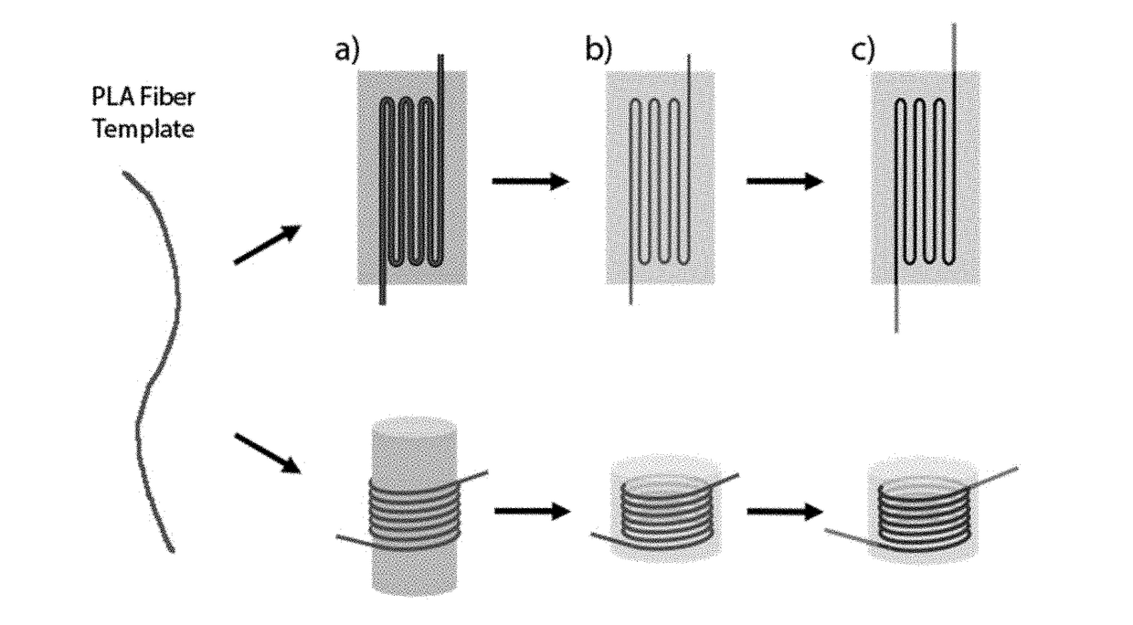
In an aspect, a method for forming a microcolumn comprises steps of: (a) providing a sacrificial fiber; (b) forming a microcolumn body around said sacrificial fiber; and (c) removing said sacrificial fiber from said microcolumn body such that a hollow channel is formed within said microcolumn body via removal of said sacrificial fiber. In any embodiment of the methods disclosed herein for forming a microcolumn, said hollow channel extends through said microcolumn body and is continuous between a first end and a second end. The first end may be an inlet and the second end may be an outlet, for example, allowing for a mobile phase to enter the hollow channel via the first end and exit via the second end.

Description

CROSS-REFERENCE TO RELATED APPLICATIONS[0001]This applicable claims the benefit of and priority to U.S. Provisional Application No. 62 / 479,360, filed Mar. 31, 2017, which is hereby incorporated in its entirety.STATEMENT REGARDING FEDERALLY SPONSORED RESEARCH OR DEVELOPMENT[0002]Not applicable.BACKGROUND OF INVENTION[0003]Recently, there has been increasing interest in the development of portable gas chromatography (GC) systems for use in the field and in the development of disposable microfluidic technology. Conventional GC systems are bulky, have high power consumption, and usually have very long analysis times, often in tens of minutes. These factors have largely limited the use of GC to a laboratory environment; thus, obtaining immediate results from field or environmental samples is difficult. Immediate results are particularly important in situations where chemicals that are dangerous to life and health may be present (e.g., in chemical workplace monitoring, industrial accident...

Claims


Application Information

Patent Timeline
IPC IPC(8): G01N30/60B01D53/02B01D53/04B01J20/285B01J20/32
CPCG01N30/6052B01D53/025B01D53/0423B01J20/285B01J20/3272G01N30/6095B01D2253/202B01D2253/34B01J2220/54B01J2220/86G01N30/6073
Inventor SUSLICK, KENNETH S.HINMAN, JORDAN J.
Owner THE BOARD OF TRUSTEES OF THE UNIV OF ILLINOIS
Learn More